

Serial Protocol Document
1. UART communication parameters
Baud rate: 115200/9600
Data bits: 8
Parity: none
Stop bits: 1
Flow control: none
2. Frame format
| Field | Header | Version | Command ID | Data length | Payload | Checksum |
|---|---|---|---|---|---|---|
| Bytes | 2 | 1 | 1 | 2 | N | 1 |
| Description | Fixed 0x5aa5 | Protocol version | Frame type | Payload length, big-endian | Payload content | Sum all bytes from header through the last byte before checksum, then modulo 256 |
Protocol notes:
All multi-byte fields in the frame use big-endian order.
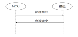
Synchronous transfer
Synchronous transfer uses the same command for request and response. One side sends a command; the other replies with the same command. Typically used for heartbeats or query commands.
As shown:
- Asynchronous transfer
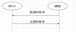
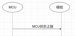
Asynchronous transfer: command M is sent, command N is the reply. Typically used for control commands—the module sends a control command; the MCU replies via a status report command.
As shown:
Module sends control command
MCU reports status
- Version usage
The version field supports extension and compatibility. Module-to-MCU frames use version 0x10; MCU-to-module frames use version 0x20.
3. Payload format
| Payload field | Data ID | Data type | Data length | Data content |
|---|---|---|---|---|
| Bytes | 1 | 1 | 2 | 1/2/4/N |
| Description | Sequence number of this data field | Type of this field | Length of data content | Hex content, big-endian |
- Data types:
| Type value | Data type | Bytes | Description |
|---|---|---|---|
| 0x01 | Bool | 1 | Content is 0x00/0x01 |
| 0x02 | value | 4 | Integer data, big-endian |
| 0x03 | String | N | String data transferred as hex |
| 0x04 | Enum | 1 | Enum type, range 0–255 |
- Protocol notes:
- Payload data content and data IDs are defined in the Thing Model document—different content maps to different data IDs and types. Example: switch, data ID 1, type bool.
- Multi-byte fields in this format use big-endian order.
- When using string type, the string content is JSON.
4. Command list
4.1 Heartbeat command
After power-on, the module sends heartbeats once per second until the MCU replies correctly. After a valid reply, the interval becomes 15 seconds, and the module continues subsequent init commands. If no valid reply is received, it keeps sending once per second.
The MCU can use heartbeat presence to judge whether the module is running normally or has reset. If there is no heartbeat, the MCU may reset the module via the hardware reset pin.
After a heartbeat connection is established, if the module receives no MCU heartbeat reply for 90 consecutive seconds (6 missed heartbeats), it reboots and waits for MCU heartbeat replies.
For a provisioned device, if the module and MCU fail to establish a connection for more than 3 minutes, the cloud marks the device offline.
Module send
| Field | Header | Version | Command ID | Data length | Data | Checksum |
|---|---|---|---|---|---|---|
| Bytes | 2 | 1 | 1 | 2 | 0 | 1 |
| Description | 0x5aa5 | 0x10 | 0x00 | 0x0000 | None | Sum all bytes from header through the last byte before checksum, then modulo 256 |
Send example: 5a a5 10 00 00 00 0f
- MCU reply
| Field | Header | Version | Command ID | Data length | Data | Checksum |
|---|---|---|---|---|---|---|
| Bytes | 2 | 1 | 1 | 2 | 0 | 1 |
| Description | 0x5aa5 | 0x20 | 0x00 | 0x0001 | 0x00: First heartbeat after MCU reboot, sent once only—used by the module to detect MCU reboot during operation 0x01: All other heartbeats return 1 | Sum all bytes from header through the last byte before checksum, then modulo 256 |
MCU first reply example: 5a a5 20 00 00 01 00 20
MCU normal reply (after first): 5a a5 20 00 00 01 01 21
4.2 Query product information
Use this command to obtain the product ID and MCU software version.
Product ID: PID (product id), generated by the Ubases IoT platform for the selected product; identifies the product type.
MCU software version: dotted decimal
x.x.x, where x is 0–99. Identifies MCU software version for firmware upgrades.Module send
| Field | Header | Version | Command ID | Data length | Data | Checksum |
|---|---|---|---|---|---|---|
| Bytes | 2 | 1 | 1 | 2 | 0 | 1 |
| Description | 0x5aa5 | 0x10 | 0x01 | 0x0000 | None | Sum all bytes from header through the last byte before checksum, then modulo 256 |
Send example: 5a a5 10 01 00 00 01
- MCU reply
| Field | Header | Version | Command ID | Data length | Data | Checksum |
|---|---|---|---|---|---|---|
| Bytes | 2 | 1 | 1 | 2 | 0 | 1 |
| Description | 0x5aa5 | 0x20 | 0x01 | N | Payload includes product KEY, MCU firmware version, and product flag | Sum all bytes from header through the last byte before checksum, then modulo 256 |
Data example:
Product info field description:
| Field | Description |
|---|---|
| pid | Product KEY / pid obtained on the Ubases IoT platform |
| ver | MCU software version |
| flag | Product flag string configured on the Ubases IoT platform |
Send example: 5A A5 20 01 00 2E 7B 22 70 69 64 22 3A 22 50 4B 68 79 51 34 62 49 22 2C 22 76 65 72 22 3A 22 31 2E 30 2E 30 22 2C 22 66 6C 61 67 22 3A 22 5A 4D 58 58 22 7D F8
4.3 Query work mode
Defines how device provisioning is triggered and indicated, as configured by the MCU. The work mode controls how Wi-Fi status is indicated and how the module enters device provisioning mode. This command queries the selected mode.
MCU–module cooperative mode:
The MCU triggers device provisioning through a UART command. The module reports its Wi-Fi status to the MCU over UART, and the MCU provides the corresponding indication.
Module self-handled mode:
Wi-Fi status is indicated by an LED driven from a module GPIO. Device provisioning is triggered through a module GPIO input.
Current module firmware does not support this mode yet; it will be updated later.
- Module send
| Field | Header | Version | Command ID | Data length | Data | Checksum |
|---|---|---|---|---|---|---|
| Bytes | 2 | 1 | 1 | 2 | 0 | 1 |
| Description | 0x5aa5 | 0x10 | 0x02 | 0x0000 | None | Sum all bytes from header through the last byte before checksum, then modulo 256 |
Send example: 5a a5 10 02 00 00 11
- MCU reply
| Field | Header | Version | Command ID | Data length | Data | Checksum |
|---|---|---|---|---|---|---|
| Bytes | 2 | 1 | 1 | 2 | 0/2 | 1 |
| Description | 0x5aa5 | 0x20 | 0x02 | 0x0000/0x0002 0x0000: MCU–module cooperative mode 0x0002: Module self-handled mode | Length 2: Data[0]: Wi-Fi status LED GPIO index Data[1]: Network-setup trigger GPIO index | Sum all bytes from header through the last byte before checksum, then modulo 256 |
MCU–module cooperative: 5a a5 20 02 00 00 21
Module self-handled, LED GPIO1, trigger GPIO5: 5a a5 20 02 00 02 01 05 29
4.4 Report network status
- Device network status:
| Network status | Description | Value |
|---|---|---|
| Status 1 | Module in BLE provisioning mode | 0x00 |
| Status 2 | Module in AP provisioning mode | 0x01 |
| Status 3 | Provisioned but not connected to router | 0x02 |
| Status 4 | Provisioned and connected to router | 0x03 |
| Status 5 | Device connected to cloud | 0x04 |
| Status 6 | Module in low-power mode | 0x05 |
| Status 7 | Module in BLE+AP coexistence provisioning mode | 0x06 |
- LED indication in module self-handled mode:
Statuses 1, 2, and 7: blink every 250 ms, then every 1000 ms in a cycle
Status 3: blink every 250 ms
Status 4: blink every 1000 ms
Status 5: solid on
Status 6: solid off
When the module detects MCU reboot or reconnect after disconnect, it actively reports Wi-Fi status to the MCU.
When Wi-Fi status changes, the module actively reports to the MCU.
If work mode is self-handled, the MCU need not implement this protocol.
On module reboot, Wi-Fi status is also reported to the MCU.
Module send
| Field | Header | Version | Command ID | Data length | Data | Checksum |
|---|---|---|---|---|---|---|
| Bytes | 2 | 1 | 1 | 2 | 1 | 1 |
| Description | 0x5aa5 | 0x10 | 0x03 | 0x0001 | Wi-Fi work status: 0x00: Status 1 0x01: Status 2 0x02: Status 3 0x03: Status 4 0x04: Status 5 0x05: Status 6 0x06: Status 7 | Sum all bytes from header through the last byte before checksum, then modulo 256 |
Send example: 5a a5 10 03 00 01 00 13
- MCU reply
| Field | Header | Version | Command ID | Data length | Data | Checksum |
|---|---|---|---|---|---|---|
| Bytes | 2 | 1 | 1 | 2 | 0 | 1 |
| Description | 0x5aa5 | 0x20 | 0x03 | 0x0000 | None | Sum all bytes from header through the last byte before checksum, then modulo 256 |
Send example: 5a a5 20 03 00 00 22
4.5 Reset network
When the module receives a reset-network command from the MCU, it clears the existing provisioning data and restarts immediately. After restarting, it completes the initialization command exchange with the MCU and enters device provisioning mode. The user can then provision it with the Ubases IoT App.
Send reset-network only after module init command exchange is complete; otherwise it is ignored.
After a network reset, the module enters BLE+AP coexistence provisioning mode.
If work mode is module self-handled, the MCU need not implement this protocol.
In module self-handled mode, holding the trigger GPIO low for 5 seconds resets Wi-Fi and starts device provisioning.
- MCU send
| Field | Header | Version | Command ID | Data length | Data | Checksum |
|---|---|---|---|---|---|---|
| Bytes | 2 | 1 | 1 | 2 | 0 | 1 |
| Description | 0x5aa5 | 0x20 | 0x04 | 0x0000 | None | Sum all bytes from header through the last byte before checksum, then modulo 256 |
Send example: 5a a5 20 04 00 00 23
- Module reply
| Field | Header | Version | Command ID | Data length | Data | Checksum |
|---|---|---|---|---|---|---|
| Bytes | 2 | 1 | 1 | 2 | 0 | 1 |
| Description | 0x5aa5 | 0x10 | 0x04 | 0x0000 | None | Sum all bytes from header through the last byte before checksum, then modulo 256 |
Send example: 5a a5 10 04 00 00 13
4.6 Select device provisioning mode
This command is similar to the reset-network command. After receiving it, the module enters the selected device provisioning mode.
The MCU may select a device provisioning mode as needed.
If work mode is module self-handled, the MCU need not implement this protocol.
Send only after module init command exchange is complete; otherwise it is ignored.
MCU send
| Field | Header | Version | Command ID | Data length | Data | Checksum |
|---|---|---|---|---|---|---|
| Bytes | 2 | 1 | 1 | 2 | 1 | 1 |
| Description | 0x5aa5 | 0x20 | 0x05 | 0x0001 | 0x00: Enter BLE provisioning mode 0x01: Enter AP provisioning mode | Sum all bytes from header through the last byte before checksum, then modulo 256 |
Send example: 5a a5 20 05 00 01 00 25
- Module reply
| Field | Header | Version | Command ID | Data length | Data | Checksum |
|---|---|---|---|---|---|---|
| Bytes | 2 | 1 | 1 | 2 | 0 | 1 |
| Description | 0x5aa5 | 0x10 | 0x05 | 0x0000 | None | Sum all bytes from header through the last byte before checksum, then modulo 256 |
Send example: 5a a5 10 05 00 00 14
4.7 Control command
Control commands apply Thing Model data to control device state.
Asynchronous protocol: after a control command, the MCU applies the corresponding Thing Model data; when values change, the MCU must report via the status report command.
Module send
| Field | Header | Version | Command ID | Data length | Data | Checksum |
|---|---|---|---|---|---|---|
| Bytes | 2 | 1 | 1 | 2 | N | 1 |
| Description | 0x5aa5 | 0x10 | 0x06 | Depends on payload types and count | Payload group | Sum all bytes from header through the last byte before checksum, then modulo 256 |
Example: Thing Model switch, data ID 1, bool type, set on (value 1).
Send example: 5a a5 10 06 00 05 01 01 00 01 01 1E
4.8 Synchronous status report
Synchronous protocol: after the MCU reports, it must wait for the module processing result.
The module should reply to every report. Do not report repeatedly before a reply.
If the network is poor and the module cannot send successfully, it returns failure after 5 seconds. The MCU must wait more than 5 seconds before reporting again.
Report data according to Thing Model data types.
A status report may include multiple Thing Model data items.
MCU send
| Field | Header | Version | Command ID | Data length | Data | Checksum |
|---|---|---|---|---|---|---|
| Bytes | 2 | 1 | 1 | 2 | 1 | 1 |
| Description | 0x5aa5 | 0x20 | 0x22 | Depends on payload types and count | Payload group | Sum all bytes from header through the last byte before checksum, then modulo 256 |
Example: Thing Model switch, data ID 1, bool type, set on (value 1).
Send example: 5a a5 20 22 00 05 01 01 00 01 01 4A
- Module reply
| Field | Header | Version | Command ID | Data length | Data | Checksum |
|---|---|---|---|---|---|---|
| Bytes | 2 | 1 | 1 | 2 | 1 | 1 |
| Description | 0x5aa5 | 0x10 | 0x23 | 0x0001 | 0x00: Report failed 0x01: Report succeeded | Sum all bytes from header through the last byte before checksum, then modulo 256 |
Send example: 5a a5 10 23 00 01 01 34
4.9 Asynchronous status report
Payload content follows the Thing Model.
Asynchronous protocol. Triggers:
- After the MCU receives a control command and executes it correctly, report changed status to the module.
- When the MCU detects Thing Model data changes, report them.
- After receiving a status query command, report all Thing Model data.
A status report may include multiple Thing Model data items.
MCU send
| Field | Header | Version | Command ID | Data length | Data | Checksum |
|---|---|---|---|---|---|---|
| Bytes | 2 | 1 | 1 | 2 | 1 | 1 |
| Description | 0x5aa5 | 0x20 | 0x07 | Depends on payload types and count | Payload group | Sum all bytes from header through the last byte before checksum, then modulo 256 |
Example: Thing Model switch, data ID 1, bool type, set on (value 1).
Send example: 5a a5 20 07 00 05 01 01 00 01 01 2F
Example: Thing Model temperature, data ID 12, value type, 26
Thing Model humidity, data ID 13, value type, 73
Send example: 5a a5 20 07 00 0F 0C 02 00 04 00 00 00 1A 0D 02 00 04 00 00 00 49 BD
4.10 Status query
Asynchronous protocol used by the module to query all Thing Model data on the MCU. After receiving this command, the MCU must report all Thing Model status.
Typical use cases:
- After first power-on and heartbeat connection, the module queries all Thing Model status.
- If the module detects MCU reboot or reconnect after disconnect, it queries all Thing Model status.
- When the cloud requests device status, the module queries all Thing Model status.
Module send
| Field | Header | Version | Command ID | Data length | Data | Checksum |
|---|---|---|---|---|---|---|
| Bytes | 2 | 1 | 1 | 2 | 0 | 1 |
| Description | 0x5aa5 | 0x10 | 0x08 | 0x0000 | None | Sum all bytes from header through the last byte before checksum, then modulo 256 |
Send example: 5a a5 10 08 00 00 17
4.11 Get local time
Local time is GMT plus the local timezone (device activation location) and daylight saving time.
Succeeds only after the module is connected to the cloud. If offline (not connected to Ubases IoT), the module returns failure.
MCU send
| Field | Header | Version | Command ID | Data length | Data | Checksum |
|---|---|---|---|---|---|---|
| Bytes | 2 | 1 | 1 | 2 | 0 | 1 |
| Description | 0x5aa5 | 0x20 | 0x1C | 0x0000 | None | Sum all bytes from header through the last byte before checksum, then modulo 256 |
Send example: 5a a5 20 1C 00 00 3B
- Module reply
| Field | Header | Version | Command ID | Data length | Data | Checksum |
|---|---|---|---|---|---|---|
| Bytes | 2 | 1 | 1 | 2 | 8 | 1 |
| Description | 0x5aa5 | 0x10 | 0x1C | 0x0008 | Data[0]: success flag, 0 fail, 1 success Data[1]: year, 0x00 = 2000 Data[2]: month, 1–12 Data[3]: day, 1–31 Data[4]: hour, 0–23 Data[5]: minute, 0–59 Data[6]: second, 0–59 Data[7]: weekday, 1–7, 1 = Monday | Sum all bytes from header through the last byte before checksum, then modulo 256 |
Example: For devices in China, local time is Beijing time (UTC+8).
Send example: 5a a5 10 23 00 01 01 34
4.12 Get current network status
- Device network status:
| Network status | Description | Value |
|---|---|---|
| Status 1 | Module in BLE provisioning mode | 0x00 |
| Status 2 | Module in AP provisioning mode | 0x01 |
| Status 3 | Provisioned but not connected to router | 0x02 |
| Status 4 | Provisioned and connected to router | 0x03 |
| Status 5 | Device connected to cloud | 0x04 |
| Status 6 | Module in low-power mode | 0x05 |
| Status 7 | Module in BLE+AP coexistence provisioning mode | 0x06 |
Returns the same network status as the report-network-status command.
Initiated by the MCU to query module network status.
MCU send
| Field | Header | Version | Command ID | Data length | Data | Checksum |
|---|---|---|---|---|---|---|
| Bytes | 2 | 1 | 1 | 2 | 0 | 1 |
| Description | 0x5aa5 | 0x20 | 0x2B | 0x0000 | None | Sum all bytes from header through the last byte before checksum, then modulo 256 |
Send example: 5a a5 20 2B 00 00 4A
- Module reply
| Field | Header | Version | Command ID | Data length | Data | Checksum |
|---|---|---|---|---|---|---|
| Bytes | 2 | 1 | 1 | 2 | 1 | 1 |
| Description | 0x5aa5 | 0x10 | 0x2B | 0x0001 | Wi-Fi work status: 0x00: Status 1 0x01: Status 2 0x02: Status 3 0x03: Status 4 0x04: Status 5 0x05: Status 6 0x06: Status 7 | Sum all bytes from header through the last byte before checksum, then modulo 256 |
Example: Module connected to router and cloud.
Send example: 5a a5 10 2B 00 01 04 3F
4.13 Get module MAC
MCU sends this command to obtain the module MAC address
MCU send
| Field | Header | Version | Command ID | Data length | Data | Checksum |
|---|---|---|---|---|---|---|
| Bytes | 2 | 1 | 1 | 2 | 0 | 1 |
| Description | 0x5aa5 | 0x20 | 0x2D | 0x0000 | None | Sum all bytes from header through the last byte before checksum, then modulo 256 |
Send example: 5a a5 20 2D 00 00 4C
- Module reply
| Field | Header | Version | Command ID | Data length | Data | Checksum |
|---|---|---|---|---|---|---|
| Bytes | 2 | 1 | 1 | 2 | 1 | 1 |
| Description | 0x5aa5 | 0x10 | 0x2D | 0x0007 | Data[0]: MAC obtain result 0x00: success, following 6 MAC bytes valid 0x01: failure, following 6 MAC bytes invalid Data[1]–Data[6]: MAC address | Sum all bytes from header through the last byte before checksum, then modulo 256 |
Example: Module MAC is 123456abcdef
Send example: 5a a5 10 2D 00 07 00 12 34 56 ab cd ef 46
4.14 Get Wi-Fi signal strength
Obtain RSSI of the router currently connected by the module
Wait until the module is connected to a router; otherwise the module returns failure.
MCU send
| Field | Header | Version | Command ID | Data length | Data | Checksum |
|---|---|---|---|---|---|---|
| Bytes | 2 | 1 | 1 | 2 | 0 | 1 |
| Description | 0x5aa5 | 0x20 | 0x24 | 0x0000 | None | Sum all bytes from header through the last byte before checksum, then modulo 256 |
Send example: 5a a5 20 24 00 00 43
- Module reply
| Field | Header | Version | Command ID | Data length | Data | Checksum |
|---|---|---|---|---|---|---|
| Bytes | 2 | 1 | 1 | 2 | 1 | 1 |
| Description | 0x5aa5 | 0x10 | 0x24 | 0x0001 | 0x00: Obtain failed Less than 0: signal strength e.g. (-20 dB) | Sum all bytes from header through the last byte before checksum, then modulo 256 |
Example: Current router RSSI is -20
Send example: 5a a5 10 24 00 01 EC 20
4.15 Wi-Fi functional test (connect specified router)
When the MCU sends a Wi-Fi functional test command, the module uses the provided router credentials to connect.
Judge connection via report-network-status. If the MCU receives a failure reply, or no router-connected status within 15 seconds, treat the test as failed.
To repeat the test while the module is connecting, the command is ignored. Reset network first, then send the Wi-Fi functional test again.
Valid only after heartbeat connection and product info query (module init complete).
SSID max 32 bytes; password max 64 bytes.
MCU send
| Field | Header | Version | Command ID | Data length | Data | Checksum |
|---|---|---|---|---|---|---|
| Bytes | 2 | 1 | 1 | 2 | N | 1 |
| Description | 0x5aa5 | 0x20 | 0x2C | N | {“ssid”:“xxx”, “password”:“xxxxxxxx”} ssid: router name password: router password | Sum all bytes from header through the last byte before checksum, then modulo 256 |
Example: {"ssid":"xxx", "password":"12345678"}
Send example: 5a a5 20 2C 00 24 7b 22 73 73 69 64 22 3a 22 78 78 78 22 2c 22 70 61 73 73 77 6f 72 64 22 3a 22 31 32 33 34 35 36 37 38 22 7d 49
- Module reply
| Field | Header | Version | Command ID | Data length | Data | Checksum |
|---|---|---|---|---|---|---|
| Bytes | 2 | 1 | 1 | 2 | 1 | 1 |
| Description | 0x5aa5 | 0x10 | 0x2C | 0x0001 | 0x00: Failed to receive router info. Check the outbound router JSON completeness. 0x01: Router info received. Use report-network-status to judge Wi-Fi connection result. | Sum all bytes from header through the last byte before checksum, then modulo 256 |
Example: Module successfully received router info
Send example: 5a a5 10 2C 00 01 01 3D
4.16 MCU OTA request
| Field | Header | Version | Command ID | Data length | Data | Checksum |
|---|---|---|---|---|---|---|
| Bytes | 2 | 1 | 1 | 2 | N | 1 |
| Description | 0x5aa5 | 0x10 | 0x0A | N | Payload includes firmware type, firmware version, and firmware key | Sum all bytes from header through the last byte before checksum, then modulo 256 |
Data example:
{
  "otatype": "module_extand_all",
  "ver": "1.0.0",
  "key": "current_upgrade_firmware_key",
  "md5": "md5_of_cloud_ota_payload"
}
Field description:
| Field | Description |
|---|---|
| otatype | OTA type: module_mcu_all = MCU OTA; module_extand_all = extension firmware OTA |
| ver | Software OTA version |
| key | Current upgrade firmware key |
| md5 | MD5 of cloud-delivered OTA data |
5. Supported AT commands
AT
| AT | |
|---|---|
| Description | Test whether the AT framework works |
| Response | OK — AT test succeeded |
| ERR — AT test failed | |
| Example | Send: AT Response: OK |
AT+KEY
| AT+KEY=DeviceID,Username,Password | |
|---|---|
| Description | Write device credentials to module flash via an AT command |
| Response | OK — device credentials written successfully |
| ERR — failed to write device credentials | |
| Example | Send: AT+KEY=HeeaUopCefFlrg,5VAVPl,HsasNdFZzTP10w Response: OK |
AT+RESTORE
| AT+RESTORE | |
|---|---|
| Description | Restore factory settings; the module restarts and enters device provisioning mode |
| Response | OK — AT succeeded |
| ERR — AT failed | |
| Example | Send: AT+RESTORE Response: OK |
AT+GDLT
| AT+GDLT | |
|---|---|
| Description | Get module boot timestamp. After power-on and successful online, the module records that online time in flash (first successful online after this boot). Offline/re-online due to network does not update it. After a new power cycle and successful online, the timestamp is updated; if not online after reboot, it is not updated. |
| Response | OK — AT succeeded |
| ERR — AT failed | |
| Example | Send: AT+GDLT Response:  |
AT+RST
| AT+RST | |
|---|---|
| Description | Reset and reboot the module |
| Response | OK — AT succeeded |
| ERR — AT failed | |
| Example | Send: AT+RST Response: OK |
AT+GMR
| AT+GMR | |
|---|---|
| Description | Get module firmware information |
| Response | OK — AT succeeded |
| ERR — AT failed | |
| Example | Send: AT+GMR Response: 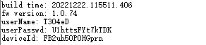 |
AT+UARTCFG
| AT+UARTCFG=baudrate | |
|---|---|
| Description | Set uart0 baud rate. Takes effect after module reset. |
| Response | OK — AT succeeded |
| ERR — AT failed | |
| Example | Send: AT+UARTCFG=115200 Response: OK |
AT+CIPSTAMAC
| AT+CIPSTAMAC? | |
|---|---|
| Description | Get module MAC address |
| Response | OK — AT succeeded |
| ERR — AT failed | |
| Example | Send: AT+CIPSTAMAC? Response:  |
AT+AILOG
| AT+AILOG=0/1/2/3/4 | |
|---|---|
| Description | Set AiLink protocol-layer log level. Lower level → fewer logs, higher efficiency; higher level → more logs, lower efficiency. |
| Response | OK — AT succeeded |
| ERR — AT failed | |
| Example | Send: AT+AILOG=4 Response: OK |
AT+AILOG
| AT+AILOG=0/1/2/3/4 | |
|---|---|
| Description | Set AiLink protocol-layer log level. Lower level → fewer logs, higher efficiency; higher level → more logs, lower efficiency. |
| Response | OK — AT succeeded |
| ERR — AT failed | |
| Example | Send: AT+AILOG=4 Response: OK |
AT+IOTLOG
| AT+IOTLOG=0/1/2/3/4 | |
|---|---|
| Description | Set IoT application-layer log level. Lower level → fewer logs, higher efficiency; higher level → more logs, lower efficiency. |
| Response | OK — AT succeeded |
| ERR — AT failed | |
| Example | Send: AT+IOTLOG=4 Response: OK |
AT+MCULOG
| AT+MCULOG=0/1/2/3/4 | |
|---|---|
| Description | Set log level for module MCU serial protocol handling. Lower level → fewer logs, higher efficiency; higher level → more logs, lower efficiency. |
| Response | OK — AT succeeded |
| ERR — AT failed | |
| Example | Send: AT+MCULOG=4 Response: OK |
6. Appendix
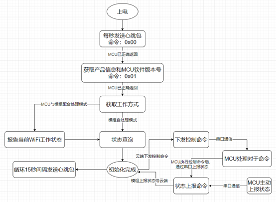
Module initialization flow
After boot, the module sends heartbeats every second, waiting for MCU replies to establish a connection.
Only after connecting to the MCU and completing initialization can the module respond to device provisioning, data exchange, and extension features. Initialization includes:
Establish heartbeat connection
Obtain product information
Configure module work mode
Report module network status (cooperative MCU–module mode)
Status query
Post-boot initialization flowchart:
Download the serial protocol document here