

Overview
Flash the Baidu RTC test firmware to the AiPi-PalChatV1 development board and you can start talking to the AI assistant "Xiao An" (小安) by voice.
Firmware flashing reference: BL602 Firmware Flashing Guide
Note
If the AiPi-PalChatV1 module you purchased already has the Baidu RTC firmware pre-installed, there is no need to flash it again — you can skip straight to Power-on Test →.
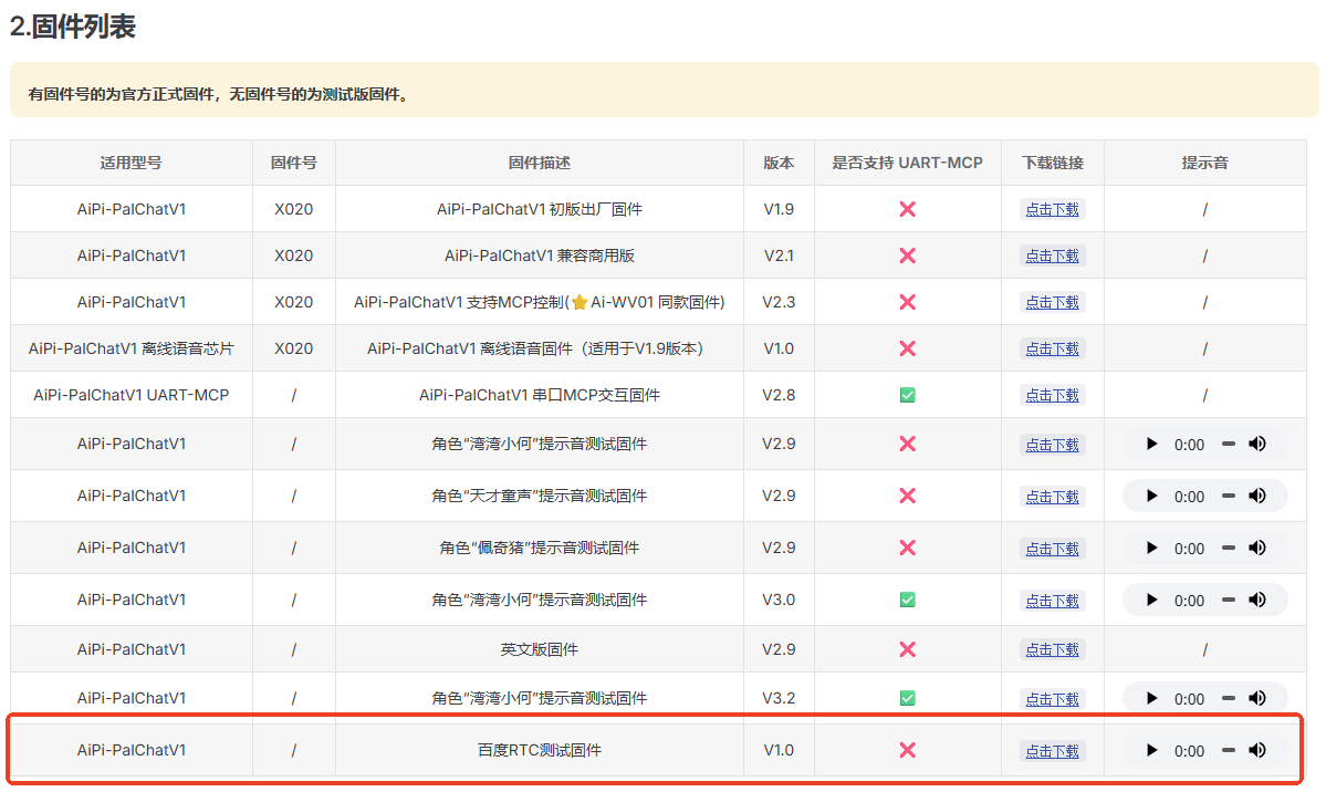
Go to Downloads — Firmware list and download the Baidu RTC test firmware.
Firmware download page: /en/aipi-palchatv1/download.html
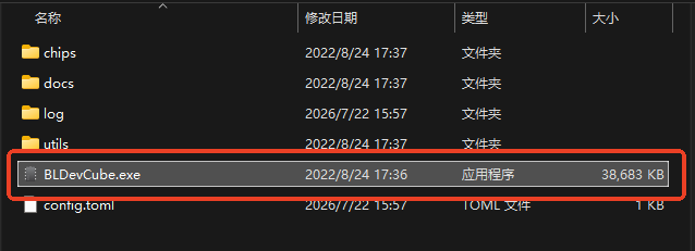
Download the BL602 firmware flashing tool:
Download BL602 Flash Download Tool
Unzip it and it is ready to use — no installation required.
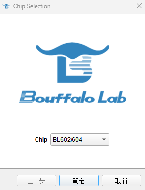
After opening the tool, select BL602/604 as the chip type.
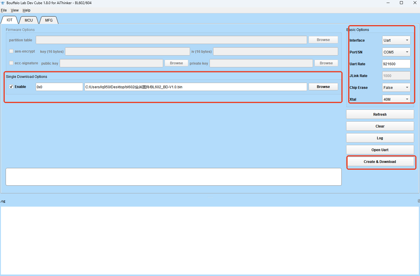
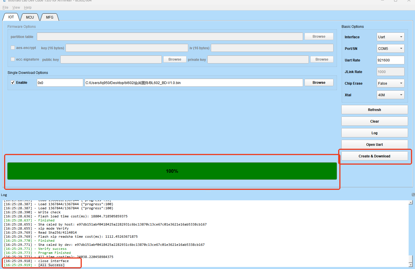
Open the flashing tool and configure it as follows:
| Section | Item | Value |
|---|---|---|
| Single Download Options | Option | Enable |
| Basic Options → Interface | Interface type | UART |
| Basic Options → Port | COM port | Select the port of your USB-to-serial adapter |
| Basic Options → UART RATE | Baud rate | 921600 |
| Basic Options → Chip Erase | Chip erase | false |
| Basic Options → XTAL | Crystal frequency | 40M |
When the configuration is done, load the firmware file you downloaded and click Start to flash; wait for it to finish.
For detailed flashing steps, see: BL602 Firmware Flashing Guide
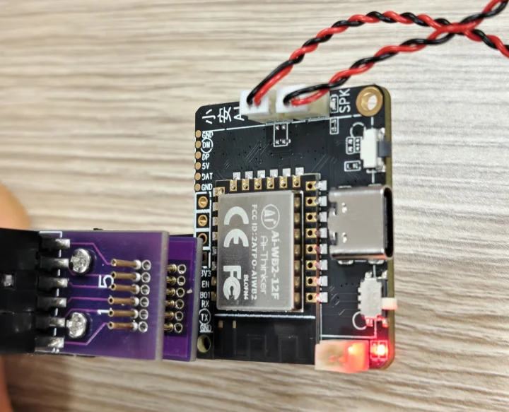
Connect the AiPi-PalChatV1 using a USB-to-serial adapter. The wiring is as follows:
| AiPi-PalChatV1 | USB-to-serial adapter | Description |
|---|---|---|
| VCC | 3.3V | Power supply positive |
| GND | GND | Power supply ground |
| TXD | RXD | Data transmit → receive |
| RXD | TXD | Data receive ← transmit |
| RTS | EN (reset) | Reset control |
| BOT | 3.3V | Mode select (flash mode) |
⚠️ Note: Connecting BOT to 3.3V puts the board into flash mode. After flashing is complete, you must disconnect the BOT pin (leave it floating) for normal operation, otherwise the device will not start properly.
After clicking Start, the progress bar reaches 100% and [All Success] appears at the bottom, which means the firmware was flashed successfully.
FAQ
Q: Flashing failed with "cannot connect to device". What should I do?
A: Check the following:
- Whether the wiring is correct (TXD ↔ RXD must be crossed)
- Whether the right COM port is selected (you can check in Device Manager)
- Whether the BOT pin is connected to 3.3V (it must be pulled high in flash mode)
- Whether the USB-to-serial adapter driver is installed
Q: The device does not start properly after a successful flash?
A: Check whether the BOT pin has been disconnected. BOT connected to 3.3V puts the board in flash mode; for normal operation it must be left floating (disconnected), otherwise the device stays in the flashing wait state.
Q: The progress bar is stuck during flashing?
A: Try lowering the baud rate (for example to 460800 or 115200), or use a higher-quality USB cable to ensure a stable power supply.
Q: Do I need to connect the BOT pin every time?
A: Only when flashing firmware do you need to connect BOT to 3.3V to enter flash mode. Disconnect it once flashing is done — subsequent normal power-ups do not require it.
Official documentation: https://aithinker.blog.csdn.net/article/details/125781602