1. Application Circuit
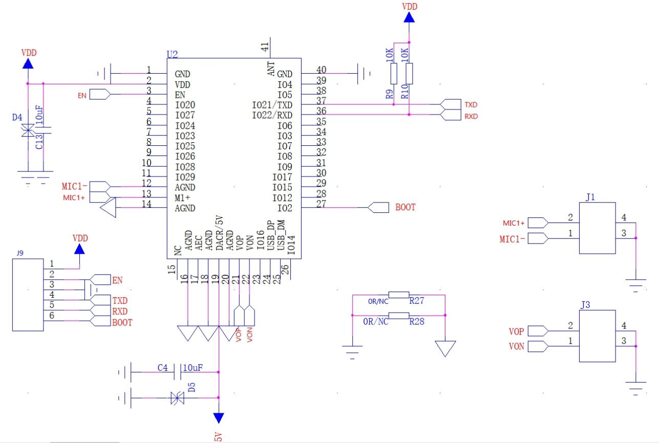
application circuit
2. Flashing Guide
▫️Flashing Preparation
- Flashing Software: Click to download
- (Little AI) Firmware: Click to view and download
- TTL to USB Tool (if not available): Click to purchase
- FT232 Driver: Click to download
- CP2102 Driver: Click to download
▫️Wiring
| USB to TTL | Ai-WV02-32S |
|---|---|
| VCC(Vo) | 3V3 |
| GND | GND |
| TXD | RXD |
| RXD | TXD |
| DTR | IO2 |
| RTS | EN |
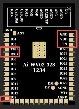
Pin Diagram
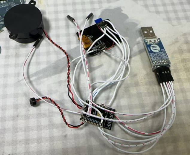
Physical wiring diagram as follows:
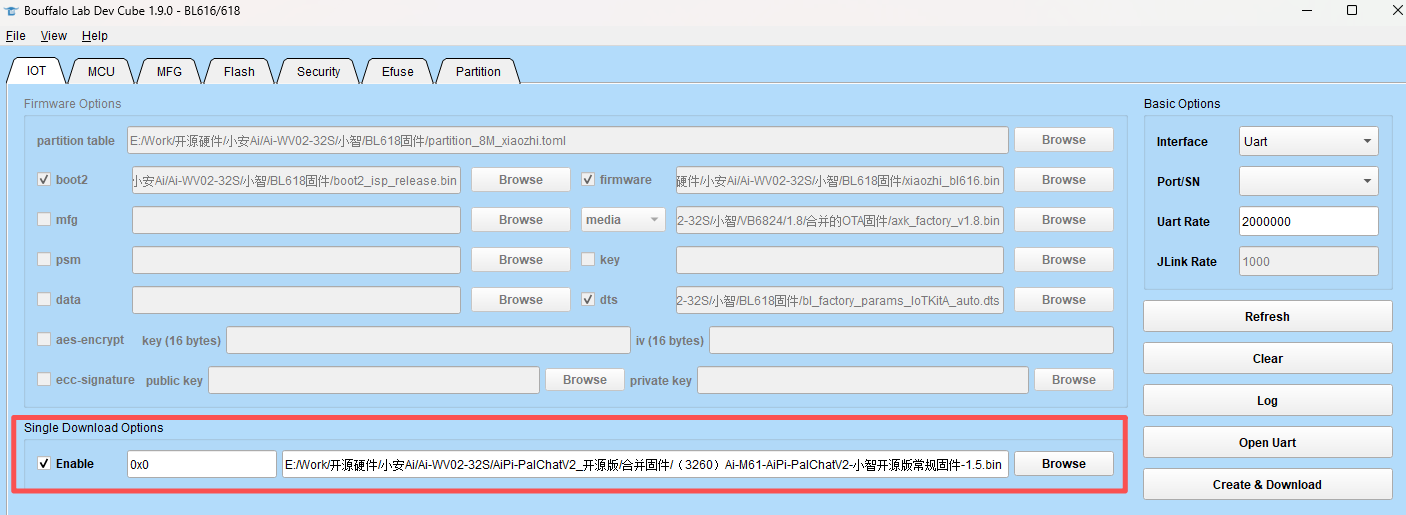
▫️Using Flashing Software
After completing the wiring, open the flashing software and follow these steps to flash:
- 1.Select the correct
COMport on the right - 2.Attention
Single Download Options - 3.Select
enable - 4.Select the corresponding synthetic firmware
- 5.click
Greate & Download - 6.Flashing completed
Operation Guide
▫️Log Viewing
After flashing is complete, remove the wiring between module IO2, EN and USB-TTL, and connect the 5V/DACR on the module to the 5V of USB-TTL,Screen Flywire and Module Connection as follows:
| USB to TTL | Ai-WV02-32S |
|---|---|
| VCC(Vo) | 3V3 |
| GND | GND |
| TXD | RXD |
| RXD | TXD |
| 5V | 5V/DACR |
| Mic Positive | MIC+ |
| Mic Negative | AGND |
| Speaker Positive | VOP |
| Speaker Negative | VON |
| Screen SPI_MOSI | IO15 |
| Screen SPI_CS | IO12 |
| Screen SPI_RS | IO16 |
| Screen SPI_SCL | IO17 |
| Screen BL_K | GND |
| Screen BL_A | VCC |
| Screen Backlight | IO2 |
Wiring Diagram
- After re-plugging the module, open the serial port assistant. It is recommended to use the Ai-Thinker Combo-AT debugging tool: Click to download
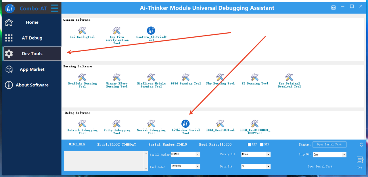
Select Ai-Thinker
Set Baud Rate
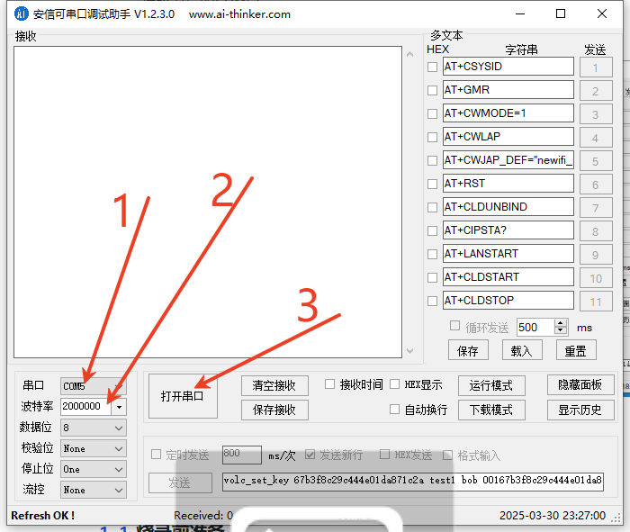
The procedure is as follows:
- Select the corresponding COM port
- Select the baud rate: 2000000
- Open the serial port
▫️Firmware Usage
The firmware instructions are consistent with AiPi-PalChatV2, Click to view AiPi-PalChatV2 instructions