

⚠️ 产品声明 / Product Disclaimer
非量产产品,仅供工程验证,不承诺符合 RoHS。 Non-mass-production product; for engineering verification only. RoHS compliance is not guaranteed.
Overview
The official base project already ships with the CH224 driver (components/ch224) and completes initialization plus the 12.2V PPS power configuration inside the sht3x_read_task task; the ch224_voltage adjustment tool is already registered in Chapter 5 of Creating an MCP Tool. This chapter covers the wiring and a hands-on test of AI-regulated supply voltage.
The CH224K is the PD sink side of USB-C: once a PD-capable charger is plugged in, it negotiates the output voltage with the charger over I²C (5V / 9V / 12V / 15V / 20V…, or even arbitrary PPS voltages in 0.1V steps). The whole board is powered through it.
Safety Notice (read before you start)
The voltage regulated by the CH224 only appears on the VOUT / GND pins and is isolated from the board's own power rail — adjusting it will not damage the board itself. But note:
- The high voltage on VOUT only feeds external loads: any device connected to VOUT/GND must withstand the target voltage (e.g. at 20V you may only connect a load rated 20V+), otherwise the external device is what burns out;
- The safety ceiling of this tool is 20V (the code enforces a 5–20V range guard and rejects anything out of range);
- Before changing the voltage, confirm the charger supports PPS or the corresponding PD profile (if not, negotiation fails and the voltage stays the same);
- When experimenting with an external load, we recommend monitoring with a multimeter / USB power meter.
The official base project already ships with the CH224 driver (components/ch224), so there is nothing to copy. In the SCBB library the module is named CH224A; if you start from an empty project, refer to:
New-Item -ItemType Directory -Force components\ch224
Copy-Item AiPi-SCBB\CH224A\axk_ch224.c components\ch224\
Copy-Item AiPi-SCBB\CH224A\axk_ch224.h components\ch224\
The official base project has already bound and initialized the I²C bus and sets 12.2V PPS power in the task (the official default). The code for starting from an empty project looks like this (the I²C macro binding is the same as for the SHT3x):
#include "stm32f10x_bsp_i2c.h"
#define AXK_CH224_DELAY_MS(x) delay_ms(x)
#define AXK_CH224_I2C_ACLL(_func, ...) bsp_i2c_##_func(__VA_ARGS__)
#define AXK_CH224_I2C_ADDR 0x22   // CH224 I2C address
Add the ch224 directory to components/CMakeLists.txt.
Initialization code (inside sht3x_read_task in freertos.c, a verified flow):
/* Initialize */
res = axk_ch224_init();
if (res != 0) { log_error("ch224 not driver"); ch224_is_init = false; }
else          { ch224_is_init = true;  log_info("ch224 init OK!"); }

/* Read the status register (0x09) */
int st = axk_ch224_get_status(AXK_CH224_REG_STATUS);
if (st < 0) log_error("ch224 status error: %d", st);
else        log_info("ch224 status: 0x%02X", st);

/* Set the PPS output voltage to 12.2V and switch to PPS mode -- this project's power configuration */
ch224_status = axk_ch224_set_pps_vout(12.2);
if (ch224_status < 0) log_error("ch224 set avs vout error: %d", ch224_status);
else                   log_info("ch224 set avs vout OK!");
ch224_status = axk_ch224_set_mode(AXK_CH224_VOUT_PPS);
if (ch224_status < 0) log_error("ch224 set mode error: %d", ch224_status);
else                   log_info("ch224 set mode OK!");
Driver API (verified against axk_ch224.h):
int axk_ch224_init(void);                                    // Initialize
int axk_ch224_get_status(axk_ch224_reg_t reg);               // Read a register (0x09 status)
int axk_ch224_set_vout(axk_ch224_vout_t VOUT);               // Fixed profile: 5V/9V/12V/15V/20V/28V
int axk_ch224_set_mode(axk_ch224_vout_t _mode);              // Operating mode: PPS or AVS
int axk_ch224_set_pps_vout(float PPS_VOUT);                  // Programmable PPS voltage (0.1V steps)
int axk_ch224_set_avs_vout(float AVS_VOUT);                  // Programmable AVS voltage
🔑 Key CH224A/Q registers (as defined in axk_ch224.h — don’t get them wrong):
Register Address Description STATUS 0x09Status register VOUT 0x0AVoltage profile / mode: 0x00~0x05= fixed profile (5V/9V/12V/15V/20V/28V),0x06= PPS mode,0x07= AVS modeAVS_MSB / AVS_LSB 0x51/0x52AVS voltage high / low byte PPS 0x53PPS target voltage, value = voltage × 10 (e.g. write 122for 12.2V)⚠️ Some “standard CH224K” references online give
0x0Bas the PPS register — that is the layout of a different chip, so don’t copy it for the CH224A/Q, or the write won’t take effect (the write is ACKed but the voltage doesn’t change).
The callback and registration for the ch224_voltage adjustment tool were completed in Chapter 5 of Creating an MCP Tool (including the 5–20V safety limit). The core logic of the tool callback is shown below (for reference):
The ch224_voltage tool: pass in a voltage value (a number from 5 to 20) to regulate the voltage; if you pass no argument, it queries the current voltage. The code adds a safety guard:
/* ---- CH224 voltage-adjust tool callback ---- */
static float current_vout = 12.2f;   // Tracks the currently configured voltage

static void ch224_voltage_set_handler(void *arg) {
  cJSON *root = (cJSON *)arg;
  cJSON *v = cJSON_GetObjectItem(root, "voltage");

  /* voltage argument present -> regulate; otherwise -> query the current voltage */
  if (v != NULL && cJSON_IsNumber(v)) {
    float target = (float)v->valuedouble;
    /* Safety limit: only 5.0 ~ 20.0V is allowed (fool-proofing, to protect the board) */
    if (target < 5.0f || target > 20.0f) {
      log_error("[ch224] voltage out of range: %.1f", target);
      emMCP_ResponseValue(emMCP_CTRL_ERROR);
      return;
    }
    /* Dynamic regulation: write the PPS voltage register first (0x53 = voltage x 10), then make sure PPS mode is active (VOUT=0x06) */
    int r1 = axk_ch224_set_pps_vout(target);
    log_info("[ch224] set_pps_vout(%.1f) = %d", target, r1);
    if (r1 == 0) {
      int r2 = axk_ch224_set_mode(AXK_CH224_VOUT_PPS);
      log_info("[ch224] set_mode(PPS) = %d", r2);
      if (r2 == 0) {
        current_vout = target;
        emMCP_ResponseValue(emMCP_CTRL_OK);
      } else emMCP_ResponseValue(emMCP_CTRL_ERROR);
    } else emMCP_ResponseValue(emMCP_CTRL_ERROR);
  } else {
    /* Query: report back the currently configured voltage */
    char rsp[32];
    snprintf(rsp, sizeof(rsp), "{\"voltage\":%.1f}", current_vout);
    emMCP_ResponseValue(rsp);
  }
}
static void ch224_voltage_check_handler(void *arg) {
  ch224_voltage_set_handler(arg);
}

/* Register */
memset(&t, 0, sizeof(t));
t.name = "ch224_voltage";
t.description = "电源输出电压调节工具,voltage参数范围5到20伏,不传voltage参数时查询当前电压";
t.inputSchema.properties[0].name = "voltage";
t.inputSchema.properties[0].description = "目标电压值5-20伏,查询当前电压时不要传此参数";
t.inputSchema.properties[0].type = MCP_SERVER_TOOL_TYPE_NUMBER;
t.setRequestHandler = ch224_voltage_set_handler;
t.checkRequestHandler = ch224_voltage_check_handler;
emMCP_AddToolToToolList(&t);
⚠️ Documenting the query behavior in the tool description matters: if the description only says “voltage regulation 5-20V”, then when you ask “what’s the voltage right now” the AI will make up a voltage value and send it over (executing it as a set). Once you add “queries the current voltage when no voltage argument is passed”, the AI will send empty arguments for a query and take the query branch.
The tool count limit
MCP_SERVER_TOOL_NUMBLE_MAXinemMCP_config.his already set to 7 (this project has 4 tools, well within it, so no change is needed); if you use manual registration mode, you must also update the ch224_voltage tool description in themcp_tools_fmtJSON.
-
The power-on log should show (actual output from this project):
[INFO] ch224 init OK! [INFO] ch224 status: 0x08 [INFO] ch224 set pps vout OK! [INFO] ch224 set mode OK!If the log only shows
ch224 set avs vout OK!(the older wording), it doesn’t affect functionality — the end behavior is the same: 12.2V PPS is requested at power-on. -
Manual serial test (USART2, 115200), starting from 5V and working up slowly:
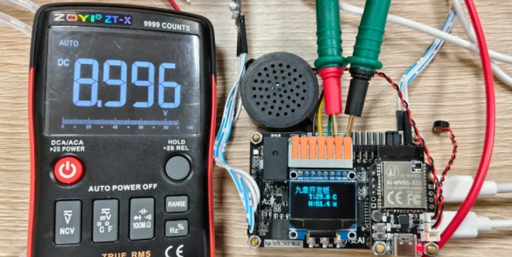
{"role":"AI","msgType":"MCP","data":{"name":"ch224_voltage","args":{"voltage":5}}} # Success -> mcp-responsive ... "data":"true" # Measure the USB-C port / onboard test point with a multimeter to confirm it really outputs 5V -
AI voice test: say “set the power to 9 volts”, “set the power to 12 volts”, “what’s the power voltage right now?”.
FAQ & Troubleshooting
🔧 Log shows ch224 not driver / status can't be read
Cause: ① wiring ② the charger doesn't support PD
Fix: ① SDA→PB6, SCL→PB7 ② you must use a PD/PPS-capable charger (an ordinary 5V charger cannot negotiate a higher voltage), plus a C-to-C cable
🔧 The voltage doesn't change after regulating
Cause: ① the charger doesn't support that profile ② PPS mode didn't take effect ③ the register was written wrong
Fix: ① confirm the charger supports PPS (look for the "PPS" marking on its nameplate) ② call set_pps_vout() first, then set_mode(AXK_CH224_VOUT_PPS), in that order ③ confirm the PPS register is 0x53 (see the register table in step ② — getting it wrong gives an ACK but the voltage doesn't change)
🔧 Replugging the charger is required after switching voltage
Cause: the CH224 only re-negotiates fully on a cold start (repowering), and writing the register at runtime can't trigger hot re-negotiation on every charger
Fix: this is normal — after switching to a new voltage for the first time, unplug the charger and plug it back in (negotiation then runs with the new register value); after that, dynamic regulation within the same profile range generally takes effect immediately. We recommend one unplug/replug per target voltage change
🔧 A fixed 9V works but PPS regulation doesn't
Cause: the charger only has fixed PD profiles and doesn't support PPS
Fix: use axk_ch224_set_vout(AXK_CH224_VOUT_9V) to go through a fixed profile (pick any of 5/9/12/15/20V); or switch to a PPS-capable charger
🔧 Negotiation fails with an A-to-C cable
Cause: a USB-A port has no PD communication
Fix: switch to a C-to-C cable, and make sure the charger supports PD/PPS
🔧 The board reboots as soon as it's set to 12V
Cause: momentary power drop / overcurrent
Fix: lower the target voltage; check whether the load is too heavy; use a higher-wattage charger (e.g. 65W)
🔧 Querying the voltage returns the "configured value", not a measured value
Cause: the driver doesn't read back the actually negotiated voltage
Fix: this is normal; current_vout records the value you set; measure the real voltage at the USB-C port with a multimeter
🔧 The 12.2V power-on default is too aggressive
Cause: the power configuration is hard-coded in the initialization
Fix: this project defaults to 12.2V (the board's design-safe value); to change the default, edit the value on the axk_ch224_set_pps_vout(12.2) line
🔧 An external device on VOUT misbehaves after regulating
Cause: the external device's voltage rating is too low
Fix: immediately set it back to 5V and power down to inspect; the VOUT output is isolated from the board's own supply, so the board itself won't burn — the external load does (see the safety notice below)
🔧 The charger negotiates but the current is insufficient
Cause: the charger's power rating is too low
Fix: use a higher-wattage charger; or reduce system power draw (turn off the LED strip, etc.)
Stated Once More
The CH224 output voltage only appears on the VOUT/GND pins and is isolated from the board's own supply — regulating it won't burn the board. But the external load connected to VOUT must be voltage-rated: start at 5V and step up one profile at a time, confirming at each step that the external load can take it; exceeding the external load's rated voltage will damage the external device (and is not covered by warranty).