

⚠️ 产品声明 / Product Disclaimer
非量产产品,仅供工程验证,不承诺符合 RoHS。 Non-mass-production product; for engineering verification only. RoHS compliance is not guaranteed.
Overview
The main MCU of the "9Mod" MCP Verification Board is the STM32F103CBTx (LQFP48, 128KB Flash / 20KB RAM). Your starting point is the 9Mod_MCPBorad base project shipped with the official repository — its MX configuration file 9Mod_MCPBorad.ioc already has the basic peripherals configured, so you don't need to create a project from scratch!
This chapter does only three things: ① get the base project from the official repository → ② open the .ioc with STM32CubeMX and understand the key configuration (USART2 + RX DMA) → ③ learn how to modify the configuration and regenerate the code. Later chapters will add features to this base project step by step until the full result is achieved.
Set Up the Environment First: Install the Software, Then Start
All commands in this tutorial (git clone, build, flash) run in PowerShell. If you haven't installed any development software yet, complete the Software Setup (Windows) chapter first (about 30 minutes), then come back to this chapter — otherwise there is nowhere to run the git clone in step ①.
Read This First to Avoid Detours
Do not use CubeMX's "New Project" to create a project yourself! The official repository's example/9Mod_MCPBorad is the "9Mod" MCP Verification Board's base project, complete with the full .ioc and base driver code (emMCP, components and Bsp are all pre-configured). When using it, copy it as your own project (see step ①) — don't modify the official source directly. A project created from scratch lacks both the peripheral configuration and modules such as components/Bsp/emMCP, so it only serves as the optional advanced exercise at the end of this chapter.
Official repository: https://github.com/Ai-Thinker-AIoT/emMCP | Official tool download: STM32CubeMX
⚠️ Must Read: USART2 Interrupt Configuration (Required by Every AI Control Case)
USART2 is the serial port between the MCU and the AI module; emMCP uses it to send and receive JSON commands, and reception uses an IDLE + DMA interrupt — you must check "USART2 global interrupt" so that the MCU is notified the moment a command arrives that reception is complete, and can process it.
⚠️ What happens if you don't check it (easy to miss in the official base project — a pitfall we hit ourselves): the MCU never gets the IDLE interrupt, so commands lie in the DMA buffer until it accumulates a full 256 bytes and only then get processed — the AI waits 5 seconds, times out, reports an error such as "failed to open the relay", and the command executes only "a while later".
Configuration steps (in CubeMX):
- Open
9Mod_MCPBorad.ioc - Pinout & Configuration → Connectivity → USART2
- In the NVIC Settings panel on the right → check "USART2 global interrupt"
- Ctrl+S to save (choose to regenerate the code)
After generation, usart.c will automatically contain:
/* USART2 interrupt Init */
HAL_NVIC_SetPriority(USART2_IRQn, 5, 0);
HAL_NVIC_EnableIRQ(USART2_IRQn);
stm32f1xx_it.c will automatically generate USART2_IRQHandler (which calls HAL_UART_IRQHandler(&huart2)).
Verify: after regenerating, build and flash, then say "open the relay" — the relay should click immediately and the AI should announce "Opened".
💡 You can also patch the code by hand (without reopening CubeMX): add the two NVIC enable lines to the USART2 branch of
HAL_UART_MspInitinusart.c, and addUSART2_IRQHandlerinstm32f1xx_it.c. But the next CubeMX regeneration will overwrite it, so checking the box in the .ioc is recommended.
First get the base project from the official repository, then copy it as your own project — don’t modify the official source directly (so you can pull official updates later).
# 1. Clone the official repository (skip if you already cloned it)
cd C:\Users\YourName
git clone https://github.com/Ai-Thinker-AIoT/emMCP.git

# 2. Copy the base project as your own project folder (use an English name, e.g. DOCS_TEST1)
Copy-Item -Recurse emMCP\example\9Mod_MCPBorad DOCS_TEST1
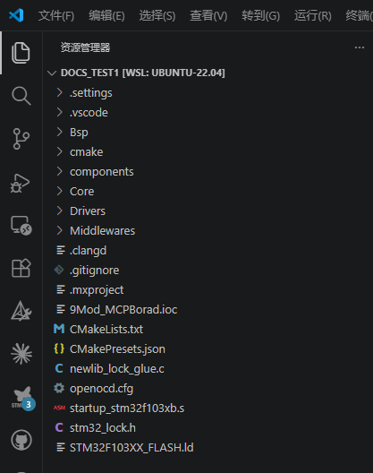
cd DOCS_TEST1

# 3. Confirm the .ioc file is there (all the basic peripherals are already configured)
dir 9Mod_MCPBorad.ioc
Run the commands above in PowerShell (press the
Winkey and search for PowerShell to open it). Don’t use Chinese characters in the project folder name (toolchains handle such paths poorly); this tutorial uses DOCS_TEST1 as an example, and every later chapter works insideC:\Users\YourName\DOCS_TEST1.
The copied project already ships with: the emMCP framework (port + uart-mcp + emMCP_config.h), the peripheral driver component library (components/: relay, SHT3x, ch224, ws2812, SSD1306, log), the board support package (Bsp/) and the base task code. Later chapters will add features to it one by one until the full result is achieved.
-
Open STM32CubeMX and click File → Open Project.
-
Select the project’s
9Mod_MCPBorad.ioc(pathC:\Users\YourName\DOCS_TEST1\9Mod_MCPBorad.ioc) — the project is on your Windows drive, so just pick it, no drive mapping needed.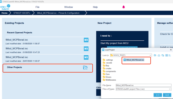
-
Once open you’ll see that all the basic peripherals are already configured:
- Pinout view: PA2/PA3 (USART2), PA9/PA10 (USART1), PA11 (WS2812) and other pins are already assigned
- Clock Configuration: HSE 8MHz × PLL9 = 72MHz
- Peripheral list on the left: USART1, USART2, SPI1, TIM1, DMA and FREERTOS are enabled
Don’t change anything for now — just get familiar with the layout.
USART2 is the channel between the STM32 and the AI module; emMCP uses it to send and receive JSON commands. Find it in CubeMX:
-
On the left, Connectivity → USART2:
- Mode: Asynchronous (async send/receive, PA2/PA3)
- Baud Rate: 115200 (the AI module’s fixed baud rate)
- Data format: 8N1, no parity (default)
-
Switch to the DMA Settings tab — you can see USART2_RX already configured:
Parameter Value DMA Request USART2_RX Channel DMA1_Channel6 Direction Peripheral to Memory Mode Normal Priority Low Data width Byte (8-bit) -
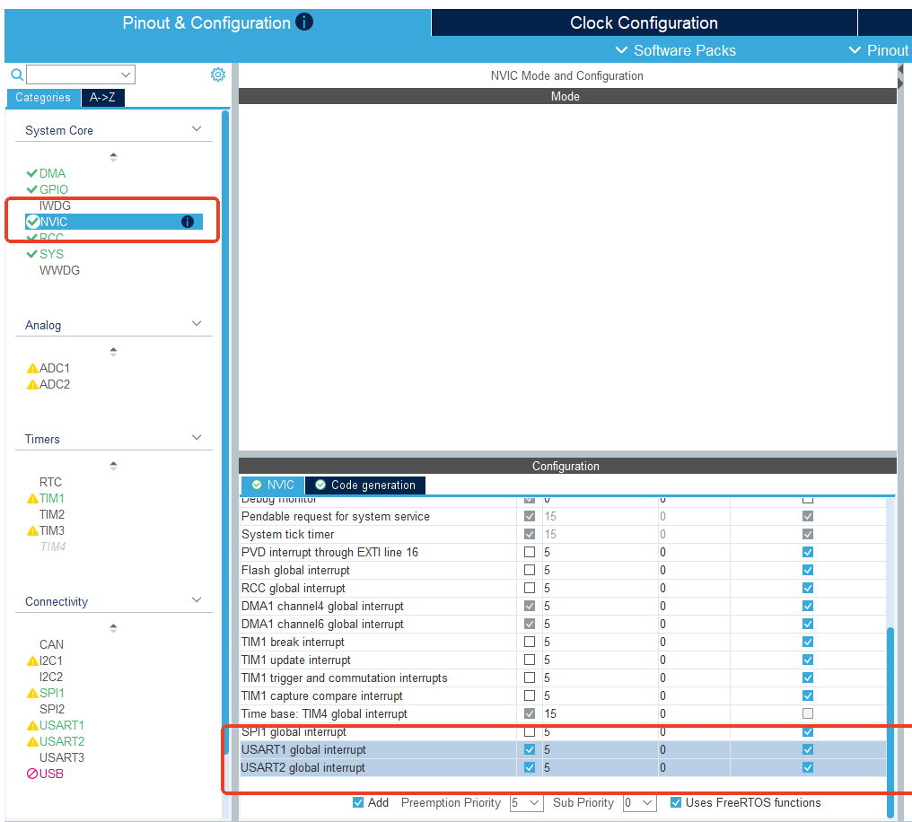
Switch to NVIC Settings:
- DMA1 channel6 global interrupt is already checked (priority 5)
- ⚠️ USART2 global interrupt — easily missed in the official base project! Make sure it is checked, and tick it if not (it drives the
HAL_UARTEx_RxEventCallbackreceive callback — see “Configuration 2” in step ⑤)
This project uses
HAL_UARTEx_ReceiveToIdle_DMA()— DMA receives the data plus a bus-idle interrupt notification. The interrupt and the DMA are both indispensable: miss either one and no AI command gets through (the classic symptom of a missing USART2 interrupt: commands execute late and the AI reports “failed” — see the relay case).
The base project’s other peripherals are configured too — get to know them with the table below (check them item by item against the official .ioc):
| Peripheral | Configuration | Notes |
|---|---|---|
| USART1 | Asynchronous, Baud Rate 1500000 | Debug serial (PA9/PA10), log output |
| SPI1 | Full-Duplex Master, Prescaler 128 | OLED screen (PA5/PA6/PA7) |
| TIM1 | PWM Generation Channel 4, Period = 90-1 | WS2812 LED strip (PA11, alternate function open-drain + high speed), TIM1_CH4 → DMA1_Channel4 (half-word) |
| DMA | USART2_RX → DMA1_Channel6, TIM1_CH4 → DMA1_Channel4 | Two DMA requests |
| GPIO PA4 | Output, label OLED_CS1, initial High | OLED chip select |
| GPIO PA1 | Output, label OLED_DC, initial High | OLED data/command select |
| GPIO PB0 | Output, label CS2, initial High | Font chip select |
| GPIO PB5 | Output | Relay control (active high) |
| GPIO PB6 / PB7 | Output | Software I²C: SDA / SCL (shared by SHT3x and CH224) |
| GPIO PB4 / PB8 | Input | Buttons (OLED page up / page down) |
| GPIO PA8 | Input | Radar Rd-03L_V2 human presence detection |
| FreeRTOS | Interface: CMSIS_V2; 3 tasks | defaultTask(24) / sht3x_read(25) / ws2812_mode(26), stack 256×4 words, heap 4096 (changed to 6656 in step ⑤) |
The base project does not enable USART3 (the IR module channel) or SPI1_TX DMA — the cases later in this tutorial don’t use those peripherals. If you need them, add them in CubeMX the same way as in this chapter’s “Advanced Exercise”.
Timebase note: SYS → Timebase Source is TIM4 (FreeRTOS occupies SysTick, so the timebase must use another timer). If you see the red warning
SysTick is used for HAL timebase and FreeRTOS, the timebase has been switched back to SysTick — just change it back to TIM4.
Once you have the .ioc you may want to change the configuration (say the baud rate, or add a pin). Here are two must-change settings to demonstrate the full loop — the base project’s default heap is too small and the USART2 receive callback isn’t enabled, so both need changing:
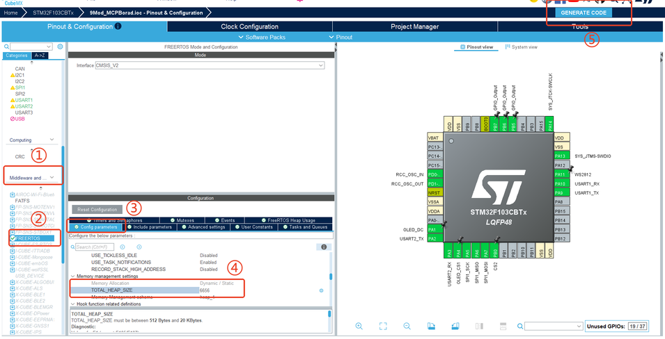
Configuration 1: change the FreeRTOS heap to 6656
-
On the left, Middleware and Software Packs → FREERTOS:
- Change the configTOTAL_HEAP_SIZE parameter from
4096to6656(the WS2812 60-LED buffer needs 2882 bytes + emMCP tool registration; keeping 4096 will break the LED strip/tools)
- Change the configTOTAL_HEAP_SIZE parameter from
Configuration 2: enable the USART2 receive callback (USART2 global interrupt) ⚠️ You must check this!
-
On the left, Connectivity → USART2 → NVIC Settings:
- Check “USART2 global interrupt” (this interrupt drives the
HAL_UARTEx_RxEventCallbackcallback: when an AI module command arrives, the MCU learns about it immediately via the IDLE interrupt and processes it)
⚠️ What happens if you don’t check it (easy to miss in the official base project — a pitfall we hit ourselves): the MCU never gets the IDLE interrupt, so commands lie in the DMA buffer until it accumulates a full 256 bytes and only then get processed — the AI waits 5 seconds, times out, reports an error such as “failed to open the relay”, and the command executes only “a while later”. See the “USART2 Interrupt Configuration” section at the start of this chapter.
- Check “USART2 global interrupt” (this interrupt drives the
-
When you’re done, click GENERATE CODE in the top right, and confirm Overwrite? → Yes in the dialog.
-
CubeMX regenerates the code:
- Code between
USER CODE BEGIN/ENDis kept as is - The configuration code in the generated areas (usart.c, FreeRTOSConfig.h, stm32f1xx_it.c, etc.) is rewritten per the new configuration —
USART2_IRQHandlerand the NVIC enable are generated automatically
- Code between
⚠️ Important: after each .ioc change and regeneration, don’t hand-edit code in the generated areas (it will be overwritten). When you need to change behavior, put it in the
USER CODEsections, or modify the upper-layer drivers (components/, Bsp/).
The structure of the base project (compared with a plain CubeMX-generated one, it adds three parts: components, Bsp and emMCP — later chapters explain them one by one):
DOCS_TEST1/
├── Core/                        ← Main program (Inc headers / Src sources)
│   └── Src/                     ← main.c, usart.c, dma.c, freertos.c (★ the tasks live here; later chapters add tools here)
├── components/                  ← ★ Peripheral driver component library (relay, SHT3x, ch224, ws2812, SSD1306, log, emMCP_config.h)
├── Bsp/                         ← ★ Board support package (soft I²C, SPI, PWM+DMA, delay)
├── Drivers/                     ← STM32 HAL library + CMSIS
├── Middlewares/                 ← FreeRTOS
├── cmake/
│   ├── gcc-arm-none-eabi.cmake  ← Cross-compile toolchain definition
│   └── stm32cubemx/             ← Source manifest CMakeLists.txt generated by CubeMX
├── CMakeLists.txt               ← Top-level build script
├── 9Mod_MCPBorad.ioc            ← ★ MX project file (the object of this chapter)
├── CMakePresets.json            ← CMake presets (Debug/Release)
├── STM32F103XX_FLASH.ld         ← Linker script
├── newlib_lock_glue.c           ← newlib glue (required for building)
└── openocd.cfg                  ← OpenOCD flashing configuration
Advanced Exercise: Creating a Project from Scratch (Optional, for Understanding Only)
When do you need to do this?
You don't need it for normal development — the main path uses the official base project's .ioc directly. This section exists so you understand "where each configuration item in the .ioc comes from", which helps when you design your own board or switch chips later. Do not use the project from this exercise as the development base for later chapters.
- Create a project: File → New Project → search for
STM32F103CBTx→ Start Project (choose Yes to initialize the peripherals). - Clock source: System Core → RCC → set High Speed Clock (HSE) to Crystal/Ceramic Resonator (the on-board 8MHz crystal).
- Debug port and timebase: System Core → SYS → set Debug to Serial Wire; set Timebase Source to TIM4.
- Clock tree: Clock Configuration page → enter 8 for HSE, select HSE for PLL Source, select x9 for PLLMUL → SYSCLK = 72MHz.
- USART2: Connectivity → USART2 → Asynchronous → baud rate 115200.
- USART2 RX DMA: DMA Settings → Add → USART2_RX → DMA1_Channel6 (peripheral→memory, Normal, Byte); in NVIC check the USART2 and DMA1 channel6 interrupts.
- Other peripherals: configure them item by item following the table in step ④ (SPI1, TIM1, USART1/3, GPIO, FreeRTOS).
- Export: Project → Settings → set Toolchain to CMake and Min CMake version to 3.22 → GENERATE CODE.
FAQ & Troubleshooting
🔧 Will the project I created myself conflict with the copied project?
Cause: several projects coexist and you don't know which one to use
Fix: use only the copied project (C:\Users\YourName\DOCS_TEST1, which comes with the .ioc + components + Bsp + emMCP). Don't keep adding features to the official source or to the exercise project
🔧 Cloning the official repository is slow / fails
Cause: network fluctuations
Fix: retry; or git clone --depth 1 https://github.com/Ai-Thinker-AIoT/emMCP.git (pulls only the latest revision)
🔧 CubeMX won't download / downloads slowly
Cause: the ST website requires an account, and access is slow on some networks
Fix: register a free ST account, sign in and download; or ask a colleague to download the installer for you (e.g. SetupSTM32CubeMX-6.18.0.exe)
🔧 The firmware package Install button is greyed out / installation fails
Cause: a network problem, or the firmware package doesn't match
Fix: try a few more times; make sure you select the F1 series V1.8.7; watch your disk space
🔧 The HSE input box on the clock tree page is greyed out
Cause: HSE isn't enabled in RCC
Fix: System Core → RCC → change High Speed Clock to Crystal/Ceramic Resonator
🔧 Red warning: SysTick is used for HAL timebase and FreeRTOS
Cause: the timebase is set to SysTick
Fix: change SYS → Timebase Source to TIM4
🔧 After generating, the build reports missing header files
Cause: a toolchain/project settings problem
Fix: make sure Toolchain is set to CMake and Min CMake version to 3.22; install the toolchain as described in Software Setup (Windows)
🔧 Features I wrote earlier are gone after regenerating
Cause: the code was written in the generated areas (outside USER CODE)
Fix: ⚠️ CubeMX preserves only what is between USER CODE BEGIN/END; everything else is rewritten. Always put custom code inside the USER CODE sections
🔧 The RTOS heap shrank after I changed the .ioc and regenerated
Cause: configTOTAL_HEAP_SIZE in the .ioc doesn't match what you expect
Fix: keep the heap size in the FreeRTOS parameters ≥ 6656 (needed for the 60-LED WS2812 buffer + emMCP tool registration)
🔧 The build succeeds, but %.1f prints nothing (e.g. {"temperature":})
Cause: newlib-nano has no floating-point formatting by default
Fix: add -u _printf_float to the linker options of both cmake toolchain files (see "Linker Option" below)
🔧 The tool runs fine, but the AI reports failure and commands are delayed
Cause: the USART2 NVIC interrupt isn't checked in the .ioc
Fix: USART2 → NVIC Settings, check "USART2 global interrupt" and regenerate (see the relay case)
🔧 The LED strip spams Failed to start DMA transmission
Cause: the WS2812 buffer uses the standard malloc (the standard heap is only ~2KB, but 60 LEDs need 2882B)
Fix: switch to pvPortMalloc in bsp_pwm_dma.c (see the memory notes in the LED strip case)
🔧 The project path contains Chinese characters/spaces and the toolchain errors out
Cause: some toolchains handle such paths poorly
Fix: keep the project directory ASCII-only with no spaces
The Right Way to Change the Configuration
To change any configuration: open the .ioc in CubeMX → change it → GENERATE CODE, and then don't hand-edit code in the generated areas (usart.c, tim.c, gpio.c, etc.). When you need to change behavior, write it in the USER CODE sections of the corresponding files, or modify the upper-layer driver/business code directly.
⚠️ Must Read: Linker Option -u _printf_float (Floating-Point printf)
The project uses newlib-nano (--specs=nano.specs), which by default contains no floating-point formatting code — %.1f in snprintf prints an empty string, turning temperature/humidity and voltage replies into invalid JSON ({"temperature":}) and making AI queries report failure.
Modify the two CMake toolchain files (both in the cmake/ directory):
# cmake/gcc-arm-none-eabi.cmake (default toolchain)
set(CMAKE_EXE_LINKER_FLAGS "${CMAKE_EXE_LINKER_FLAGS} --specs=nano.specs -u _printf_float")

# cmake/starm-clang.cmake (if you use STARM_HYBRID)
set(CMAKE_EXE_LINKER_FLAGS "${CMAKE_EXE_LINKER_FLAGS} --gcc-specs=nano.specs -u _printf_float")
After rebuilding, FLASH usage grows by about 4~5KB (61% → 66%) and %.1f prints again.
⚠️ Must Read: The Two Heaps in 20KB of RAM (Memory Accounting)
The STM32F103 has only 20KB of RAM (this project already uses 92%), and the standard heap (malloc) and the FreeRTOS heap (pvPortMalloc) are separate:
| Heap | Size | Purpose |
|---|---|---|
| Standard heap | About 2144 bytes (the remaining space at the end of RAM) | cJSON message parsing (all emMCP tool calls depend on it) |
| FreeRTOS heap | 6656 bytes (configTOTAL_HEAP_SIZE) | emMCP tool registration + WS2812 LED strip buffer (60 LEDs = 2882 bytes) |
⚠️ The WS2812 buffer must be allocated with pvPortMalloc (bsp_pwm_dma.c); using the standard malloc fails (2882 > 2144), which makes the LED strip spam Failed to start DMA transmission, and once cJSON gets squeezed out the temperature/humidity and color-tuning tools fail intermittently. See the "WS2812 Buffer Memory Allocation" section of the LED strip case.