

⚠️ 产品声明 / Product Disclaimer
非量产产品,仅供工程验证,不承诺符合 RoHS。 Non-mass-production product; for engineering verification only. RoHS compliance is not guaranteed.
Overview
The official base project already ships with the relay driver (components/relay) and initializes it inside the task; the relay tool was already registered in Chapter 5 of Creating an MCP Tool. This chapter: wiring (PB5) → confirm the tool → implement AI voice control of the relay on/off.
The example project already ships with the relay driver (components/relay, the version that calls STM32 HAL directly), nothing to copy or modify. The driver interface is shown below (read it to see how it works):
/* components/relay/relay.c — direct HAL-call version */
#include "relay.h"
#include "gpio.h"
#include "log.h"
#include "stm32f1xx_hal_gpio.h"

static unsigned char axk_relay_state = 0;

/* Set the relay to the open state at power-on (PB5 output low) */
void axk_relay_init(void) {
  if (HAL_GPIO_ReadPin(GPIOB, GPIO_PIN_5) != GPIO_PIN_RESET) {
    HAL_GPIO_WritePin(GPIOB, GPIO_PIN_5, GPIO_PIN_RESET);
    return;
  }
}

/* Set the relay: state=ON(1) pulls in, state=OFF(0) releases */
void axk_relay_set(unsigned char state) {
  axk_relay_state = state;
  HAL_GPIO_WritePin(GPIOB, GPIO_PIN_5, state);
}

void axk_relay_toggle(void) {
  axk_relay_state = !axk_relay_state;
  HAL_GPIO_WritePin(GPIOB, GPIO_PIN_5, axk_relay_state);
}

unsigned char axk_relay_get(void) { return axk_relay_state; }
The relay.h header interface:
#ifndef __RELAY_H__
#define __RELAY_H__

#define ON 1    // Pull in
#define OFF 0   // Release

void axk_relay_init(void);
void axk_relay_set(unsigned char state);
unsigned char axk_relay_get(void);
void axk_relay_toggle(void);
#endif
The example project’s components/CMakeLists.txt already includes the relay directory (source files and header paths), no changes needed.
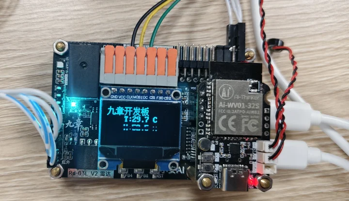
🧩 The relay on the “9Mod” MCP Verification Board is already wired onboard (controlled by PB5), so no wiring is needed. The table below is for reference, to learn the pins or to extend the board with an external relay module.
| Relay Module | Connect to Board | Description |
|---|---|---|
| IN / SIG (signal input) | PB5 | High level pulls in, low level releases |
| VCC | 5V | Powers the relay coil |
| GND | GND | Common ground |
| COM / NO (contacts) | Switched load circuit | e.g. a light bulb: wire the live line in series through COM–NO |
⚠️ Safety note: relay contacts are often used to switch 220V AC appliances, so always disconnect the power before wiring, and insulate any bare wire ends. Beginners should first test with an LED + resistor or a buzzer as the load, and only connect mains power once the logic is confirmed correct.
The relay tool’s callbacks and registration were already completed in Chapter 5 of Creating an MCP Tool (relay_set_handler controls the relay, relay_check_handler queries its state). The core action inside the tool callback is simply calling the driver:
/* Call the driver inside the tool callback */
if (strcmp(s, "on") == 0) { relay_on = true; axk_relay_set(ON); log_info("Relay -> ON"); }
else if (strcmp(s, "off") == 0) { relay_on = false; axk_relay_set(OFF); log_info("Relay -> OFF"); }

/* Call once during task initialization */
axk_relay_init();
Don’t forget to
#include "relay.h"at the top of freertos.c, and to define the global statestatic bool relay_on = false;.
-
Build and flash (see Development Guide), then power on the board.
-
Manual verification (commonly called a “smoke test” — with no AI involved, send a command straight over the serial port first to confirm the hardware and the tool logic work): connect a serial assistant to USART2 (115200) and send:
{"role":"AI","msgType":"MCP","data":{"name":"relay","args":{"state":"on"}}}The relay should pull in; change
"on"to"off"and the relay releases. -
AI voice control: once the AI module is connected to the network, say to the module:
- “Hello Xiao An” (the wake word;
WakeUPappears in the log) - “Turn on the relay” → the relay pulls in
- “Turn off the relay” → the relay releases
- “What state is the relay in now?” → the AI calls the check callback and replies
- “Hello Xiao An” (the wake word;
The AI won’t execute the command? ① The module is offline → configure the network again; ② The tool was not registered successfully → check the log for
mcp-tool sent; ③ The description doesn’t match → write the tool description clearly (“turn the relay on/off”), because the AI relies on the description to understand the tool; ④ Manual JSON works but voice doesn’t → confirm the module firmware is the UART-MCP version.
FAQ & Troubleshooting
🔧 The relay does not actuate (no click)
Cause: ① Insufficient module power ② Wrong trigger polarity ③ No common ground
Fix: ① The module's VCC must be 5V (at 3.3V the coil cannot pull in hard enough) ② Some modules are low-level triggered — move the wire to the normally closed terminal, or change the axk_relay_set logic ③ GND must be common with the board
🔧 The relay twitches once at power-on
Cause: The pin level is undefined the instant the chip resets
Fix: This is normal; to eliminate it, add a pull-down resistor to the module's IN pin, or just accept it (in this project axk_relay_init pulls the pin low right after power-on)
🔧 Manual JSON works, AI voice doesn't
Cause: The tool description is unclear, or the module was not woken up
Fix: Say "Hello Xiao An" first to wake it up; write the description in plain words such as "turn the relay on/off"
🔧 The relay pulls in but the load doesn't work
Cause: The contacts are wired wrong
Fix: COM and NO are the normally open contacts (they conduct only when the relay pulls in); wire to COM/NC for an always-on connection; also make sure the load circuit is powered
🔧 The relay actuates, but the AI announces "turn-on failed"; and the command takes a while to execute
Cause: ⚠️ The USART2 interrupt is not enabled (USART2 global interrupt is not ticked in the .ioc file)
Fix: In STM32 Project Creation, tick USART2 global interrupt and regenerate the code — this is the easiest pitfall to hit in this project
🔧 The relay switches on and the AI announces normally, but long-message tools such as temperature/humidity or the LED strip always fail
Cause: Bytes are lost while receiving messages
Fix: If the serial log is garbled or bytes go missing, see the log mutex note in the Temperature/Humidity Case
🔧 The module gets hot / smells odd when switching 220V appliances
Cause: The current exceeds the relay contact rating
Fix: The SRD-05VDC contact rating is about 10A; for high-power loads use a larger relay, and always wire with the power disconnected
🔧 The LED burned out during testing
Cause: The LED had no current-limiting resistor in series
Fix: An LED must have a resistor in series (220Ω~1kΩ), or just use a buzzer module / a multimeter's continuity (buzzer) mode
🔧 PB5 stays high
Cause: PB5 is not configured in CubeMX, or its initial state is wrong
Fix: Confirm PB5 is GPIO_Output in the .ioc file (in this project it starts low, i.e. the open state)
High-Voltage Load Test Order
Test with no load first (confirm the relay pulls in/releases correctly) → then connect an LED + resistor or a buzzer → once the logic is confirmed, connect the high-voltage load last, and always wire with the power disconnected.