

⚠️ 产品声明 / Product Disclaimer
非量产产品,仅供工程验证,不承诺符合 RoHS。 Non-mass-production product; for engineering verification only. RoHS compliance is not guaranteed.
Overview
The official base project already ships with the WS2812 driver (components/ws2812, TIM1_CH4 PWM + DMA); the ledstrip color tool was already registered in Chapter 5 of Creating an MCP Tool. This chapter covers the wiring and puts AI light control to the test — the strip is off by default and is lit by AI control (ledstrip tool: on/off, color, brightness).
Every LED on a WS2812 strip contains its own chip, and the data line is cascaded serially. Its data signal needs very precise timing (800kHz data rate), so it is generated with TIM1_CH4 PWM + DMA — which is exactly why TIM1 PWM CH4 is configured in CubeMX.
The official base project already ships with the WS2812 driver (components/ws2812, including the color_mode color tool), nothing to copy. You only need this when starting from a blank project:
mkdir -p components/ws2812
cp ~/AiPi-SCBB/WS2812/axk_ws2812.c components/ws2812/
cp ~/AiPi-SCBB/WS2812/axk_ws2812.h components/ws2812/
cp ~/AiPi-SCBB/WS2812/color_mode.c components/ws2812/
cp ~/AiPi-SCBB/WS2812/color_mode.h components/ws2812/
The official base project already has CMake and initialization configured. In this project the strip is off by default: the ws2812_modeTask task only initializes and sets “all off”, it runs no animation — the strip lights up only when the AI controls it through the ledstrip tool. The code (the real code of ws2812_modeTask in freertos.c):
axk_ws2812_init(&ws2812);
/* Off by default: lit only when the AI controls it (ledstrip tool) */
axk_ws2812_set_all_pixels_color(0, 0, 0, 0.0f);
for (;;) {
  osDelay(pdMS_TO_TICKS(15));
}
The low-level capability the driver relies on (already implemented in Bsp/pwm_dma, which uses the TIM1 DMA channel internally):
void bsp_pwm_dma_init(uint16_t led_num);   // Allocate the LED buffer (FreeRTOS heap)
int  bsp_pwm_dma_with_num(void);           // Feed the color buffer into the TIM1 PWM DMA
// In the header file:
#define WS2812_MAX_NUM 60                 // Up to 60 LEDs on the strip
// CODE0 / CODE1 = duty counts of the 0 bit and the 1 bit (0.35us / 1.25us @ 90 counts, 800kHz)
Add the ws2812 directory to components/CMakeLists.txt; confirm Bsp/CMakeLists.txt already has pwm_dma.
Initialization (the real code of ws2812_modeTask in freertos.c):
/* Define the strip object: 60 LEDs */
axk_ws2812_strip_t ws2812 = {.led_count = WS2812_MAX_NUM};

/* Initialize */
axk_ws2812_init(&ws2812);
Driver API (verified against axk_ws2812.h):
int  axk_ws2812_init(axk_ws2812_strip_t *strip);            // Initialize
void axk_ws2812_show_leds(void);                             // Refresh the display
void axk_ws2812_set_pixel_color(index, r, g, b);             // Set the color of LED #index
void axk_ws2812_set_all_pixels_color(r, g, b, brightness);   // ★ All LEDs one color (0~255, brightness 0~1)
void axk_ws2812_set_pixel_color_hsv(index, h, s, v);         // HSV mode
void axk_ws2812_set_led_count(uint8_t count);                // Change the LED count
🧩 The “9Mod” MCP Verification Board has no onboard LED strip — the strip is an external module (DIN → PA11); just wire it up and it works. See the note below for power considerations.
| WS2812 LED Strip | Connect to Board |
|---|---|
| DIN (data input) | PA11 (TIM1_CH4) |
| VCC (power) | 5V (long strips must be powered externally) |
| GND | GND (common ground is required, otherwise the data won’t be recognized) |
⚠️ Power note: one WS2812 LED at full white draws about 60mA, so 60 LEDs draw 3.6A — the small onboard regulator can’t handle it. In your experiments connect only 10~30 LEDs, or power the strip from a separate 5V supply with a common ground to the board.
The ledstrip color tool’s callbacks and registration were already completed in Chapter 5 of Creating an MCP Tool. The core logic of the tool callback is below (read it to see how it works):
This project already has a complete ledstrip tool (freertos.c) supporting four modes — on/off, color, brightness and query. The core logic is below:
/* ---- LEDStrip MCP tool callback (WS2812 LED strip control) ---- */
static uint8_t led_r = 255, led_g = 0, led_b = 0;
static uint8_t led_brightness = 50;

static void ledstrip_set_handler(void *arg) {
  cJSON *root = (cJSON *)arg;
  cJSON *mode_item = cJSON_GetObjectItem(root, "mode");
  log_info("[ledstrip] called, mode=%s", mode_item && cJSON_IsString(mode_item) ? mode_item->valuestring : "(null)");
  if (mode_item && cJSON_IsString(mode_item)) {
    const char *m = mode_item->valuestring;
    if (strcmp(m, "on") == 0) {
      led_on = true;
      axk_ws2812_set_all_pixels_color(led_r, led_g, led_b, led_brightness / 100.0f);
    } else if (strcmp(m, "off") == 0) {
      led_on = false;
      axk_ws2812_set_all_pixels_color(0, 0, 0, 0.0f);
    } else if (strcmp(m, "set") == 0) {
      cJSON *r = cJSON_GetObjectItem(root, "r");
      cJSON *g = cJSON_GetObjectItem(root, "g");
      cJSON *b = cJSON_GetObjectItem(root, "b");
      if (r && cJSON_IsNumber(r)) led_r = (uint8_t)r->valueint;
      if (g && cJSON_IsNumber(g)) led_g = (uint8_t)g->valueint;
      if (b && cJSON_IsNumber(b)) led_b = (uint8_t)b->valueint;
      cJSON *br = cJSON_GetObjectItem(root, "brightness");
      if (br && cJSON_IsNumber(br)) led_brightness = (uint8_t)br->valueint;
      log_info("[ledstrip] set: r=%d g=%d b=%d br=%d", led_r, led_g, led_b, led_brightness);
      led_on = true;
      axk_ws2812_set_all_pixels_color(led_r, led_g, led_b, led_brightness / 100.0f);
    } else if (strcmp(m, "query") == 0) {
      char rsp[128];
      snprintf(rsp, sizeof(rsp), "{\"mode\":\"%s\",\"on\":%s,\"r\":%d,\"g\":%d,\"b\":%d,\"brightness\":%d}", "set", led_on ? "true" : "false", led_r, led_g, led_b, led_brightness);
      emMCP_ResponseValue(rsp);
      return;
    } else { emMCP_ResponseValue(emMCP_CTRL_ERROR); return; }
    emMCP_ResponseValue(emMCP_CTRL_OK);
    return;
  }
  emMCP_ResponseValue(emMCP_CTRL_ERROR);
}

/* Register (4 properties: r/g/b/brightness; see [Creating an MCP Tool](./create-mcp-tool) for how to register) */
memset(&t, 0, sizeof(t));
t.name = "ledstrip";
t.description = "WS2812灯带控制工具,RGB颜色(r/g/b:0-255)、可选mode(on/off)、brightness(0-100)";
t.inputSchema.properties[0].name = "r";
t.inputSchema.properties[0].description = "红色分量 0-255";
t.inputSchema.properties[0].type = MCP_SERVER_TOOL_TYPE_NUMBER;
t.inputSchema.properties[1].name = "g";
t.inputSchema.properties[1].description = "绿色分量 0-255";
t.inputSchema.properties[1].type = MCP_SERVER_TOOL_TYPE_NUMBER;
t.inputSchema.properties[2].name = "b";
t.inputSchema.properties[2].description = "蓝色分量 0-255";
t.inputSchema.properties[2].type = MCP_SERVER_TOOL_TYPE_NUMBER;
t.inputSchema.properties[3].name = "brightness";
t.inputSchema.properties[3].description = "亮度 0-100";
t.inputSchema.properties[3].type = MCP_SERVER_TOOL_TYPE_NUMBER;
t.setRequestHandler = ledstrip_set_handler;
t.checkRequestHandler = ledstrip_check_handler;
emMCP_AddToolToToolList(&t);
Why is the strip off by default: the
ws2812_modeTasktask runs no animation (unlike the gradient animation in the official example, which this project has removed), so the strip is dark as soon as the board powers up; when the AI calls theledstriptool (modeset to on/set) the strip lights up and keeps its color, and atmode=offit goes dark. Theled_onflag records the AI control state for queries (mode=query).
-
Build and flash. The strip is off by default at power-on (this project has removed the default animation); once you light it up over the serial port or by AI control, the driver is working.
-
Manual serial test (USART2, 115200):
# All LEDs pure red, brightness 50% {"role":"AI","msgType":"MCP","data":{"name":"ledstrip","args":{"mode":"set","r":255,"g":0,"b":0,"brightness":50}}} # Turn off the strip {"role":"AI","msgType":"MCP","data":{"name":"ledstrip","args":{"mode":"off"}}} # Query the state {"role":"AI","msgType":"MCP","data":{"name":"ledstrip","args":{"mode":"query"}}} -
AI voice test: say “Set the LED strip to blue, brightness 30%”, “Turn off the LED strip”, “Set the light to warm yellow” (warm yellow ≈ r=255, g=180, b=50).
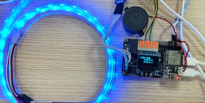
Troubleshooting:
| Symptom | What to check |
|---|---|
| The strip doesn’t light | Is DIN connected to PA11; is the strip GND common with the board; check the TIM1_CH4 DMA (DMA1_Channel4, half-word, memory→peripheral) and interrupt configuration |
| Long strip is dim / flickers | Insufficient power; supply a separate external 5V and common the ground |
FAQ & Troubleshooting
🔧 The strip doesn't light at all
Cause: ① DIN not connected to PA11 ② No common ground ③ Insufficient power
Fix: ① DIN→PA11 ② The strip GND and the board must be common ground ③ Short strips can use 5V directly, long strips need a separate supply
🔧 Only the first few LEDs light up / the color is wrong
Cause: ① The data line is connected backwards (wired to DOUT) ② The LED count setting doesn't match
Fix: ① Connect DIN, not DOUT ② led_count must match the real LED count (60 by default)
🔧 The strip is dim / flickers
Cause: Insufficient power
Fix: A single LED at full white draws about 60mA, and 60 LEDs draw 3.6A; a long strip must be powered from an external 5V supply with a common ground to the board
🔧 The color is inaccurate after setting it (red and green swapped)
Cause: The GRB order in the driver
Fix: The WS2812 data order is G-R-B (this project's driver already handles it this way); if you switch to another chip type (e.g. SK6812 is RGB), change the byte order in the driver
🔧 log_error: Failed to allocate memory for WS2812 buffer (or Failed to start DMA transmission flooding the log)
Cause: The standard malloc heap is too small — of the 20KB RAM the standard heap holds only about 2144 bytes, while the buffer for 60 LEDs needs 2882 bytes
Fix: You must allocate from the FreeRTOS heap with pvPortMalloc (see the "WS2812 buffer memory" note below); also confirm configTOTAL_HEAP_SIZE ≥ 6656
🔧 The strip switches on/off but the color won't change
Cause: ① The tool isn't registered ② The parameters are wrong
Fix: ① Check the log for mcp-tool sent ② Make sure the AI sends mode=set together with r/g/b (numeric); verify with the manual serial test command
🔧 Some strips don't respond when driven at 3.3V
Cause: Some strips need a 5V logic level
Fix: Add a level shifter between PA11 and DIN (or pick a 3.3V-compatible strip); this project's PA11 uses an open-drain output + pull-up, which works with most strips
🔧 After turning the strip off and on again, the color is not the previous one
Cause: The state is lost once power is removed
Fix: This is normal; the led_r/led_g/led_b variables live in RAM and are gone when power drops. Remembering them would require writing Flash/EEPROM
🔧 The board resets when all 60 LEDs are lit
Cause: Excessive current causes the 5V rail to drop
Fix: Reduce led_count, lower the brightness, or power externally — pick one
Safe Starting Point for LED Strip Testing
For beginners: start with 10 LEDs at 30% brightness. Use {"mode":"set","r":255,"g":0,"b":0,"brightness":30} to confirm a single color first, then play with rainbow/breathing effects, and only then move on to a long strip + external power.
⚠️ Must Read: WS2812 Buffer Memory Allocation (the Memory Budget of 20KB RAM)
Symptom: the log floods with Failed to start DMA transmission; after changing the LED count it becomes WS2812 buffer not allocated (malloc failed); afterwards tools such as temperature/humidity and color control also fail intermittently.
Root cause: the STM32F103 has only 20KB RAM, and this project already uses 92% of it. Memory is split across two heaps:
| Heap | Size | Who uses it |
|---|---|---|
Standard heap (malloc) | about 2144 bytes | cJSON message parsing (all parameter parsing for emMCP tool calls depends on it) + other malloc calls |
FreeRTOS heap (pvPortMalloc) | 6656 bytes (configTOTAL_HEAP_SIZE) | emMCP tool registration + WS2812 buffer |
The WS2812 buffer = LED count × 24 × 2 bytes: 60 LEDs = 2882 bytes > the 2144-byte standard heap. If bsp_pwm_dma_init allocates with the standard malloc, it is bound to fail — DMA starts with a NULL address and the error floods the log; more subtly, cJSON is squeezed into those 2144 bytes, so parsing long messages (color/query with Chinese parameters) fails to allocate → the tool fails silently.
Fix: allocate the buffer from the FreeRTOS heap in Bsp/pwm_dma/stm32f10x_pwm_dma.c:
/* bsp_pwm_dma_init: malloc → pvPortMalloc */
buffer_ptr = (uint16_t *)pvPortMalloc((ws2812_max_led_num * 24 + 1) * sizeof(uint16_t));
if (buffer_ptr == NULL) {
  log_error("Failed to allocate memory for WS2812 buffer");
}

/* bsp_pwm_dma_deinit: free → vPortFree */
vPortFree(buffer_ptr);
Also add a null-pointer guard at the top of bsp_pwm_dma_with_num() (so DMA never starts with a NULL address):
if (buffer_ptr == NULL) {
  log_error("WS2812 buffer not allocated (malloc failed)");
  return -1;
}
📌 Memory budget summary: the 2144-byte standard heap must be left to cJSON; WS2812 (2882B) and the emMCP tools (about 1~2KB) share the 6656-byte FreeRTOS heap. Before adding more peripherals or features, do the memory math first — only about 1.5KB of RAM headroom is left (92% usage).
Conclusion
That completes all nine tutorials. You have now mastered the five-piece SCBB module porting routine: copy the module → hook up the BSP macros → add CMake → initialize → register the MCP tool. Next you could try: adding more parameters to a tool (such as a relay timer), a custom OLED page, or porting to another STM32 chip.