

Contributed by bzhou830, organized by Ai-Thinker
[Peripheral Porting] Ai-WB2 + MPU6050
1. MPU6050 Introduction
The MPU-60X0 is the world's first 9-axis motion processing sensor. It integrates a 3-axis MEMS gyroscope, a 3-axis MEMS accelerometer, and an expandable digital motion processor DMP (Digital Motion Processor), and can connect a third-party digital sensor, such as a magnetometer, via the I2C interface. With the expansion, it can output a 9-axis signal through its I2C or SPI interface (the SPI interface is only available on the MPU-6000). The MPU-60X0 can also connect non-inertial digital sensors, such as pressure sensors, through its I2C interface. The MPU-60X0 uses three 16-bit ADCs (0~65535) for the gyroscope and accelerometer respectively, converting the measured analog quantities into outputtable digital quantities. To accurately track fast and slow motion, the measurement ranges of the sensors are user-controllable: the gyroscope can measure ±250, ±500, ±1000, ±2000 °/sec (dps), and the accelerometer can measure ±2, ±4, ±8, ±16g. The chip size is 4×4×0.9mm, packaged in QFN (quad flat no-lead package), can withstand shocks of up to 10000g, and has a programmable low-pass filter. The internal block diagram of the MPU6050 is shown below:
Of the pins you need to know: SCL and SDA are the IIC interface connecting to the MCU, through which the MCU controls the MPU6050. There is another IIC interface, AUX_CL and AUX_DA, which can be used to connect external slave devices such as a magnetometer, thus forming a 9-axis sensor. VLOGIC is the IO port voltage; this pin can go as low as 1.8V, and we usually connect it directly to VDD. AD0 is the address control pin of the IIC interface (connecting to the MCU); it controls the lowest bit of the IIC address. If connected to GND, the IIC address of the MPU6050 is 0X68; if connected to VDD, it is 0X69. Note that the addresses 0x68 and 0x69 here do not include the lowest bit used for data transmission, so they are not 8-bit data: 0x68 represents 110 1000 and 0x69 represents 110 1001; the lowest bit is usually used to indicate whether the IIC master is reading or writing data. Self-test is a built-in test; its purpose is to test the mechanical and electrical structure of the sensor, that is, to check whether the chip is damaged through self-test. Once self-test is activated, the circuit makes the sensor work and produces output signals. For details on self-test, the official chip datasheet has a detailed description, as follows:
- Gyroscope Self-Test When self-test is activated, the on-board electronics will actuate the appropriate sensor. This actuation will move the sensor’s proof masses over a distance equivalent to a pre-defined Coriolis force. This proof mass displacement results in a change in the sensor output, which is reflected in the output signal. The output signal is used to observe the self-test response. The self-test response is defined as follows: Self-test response = Sensor output with self-test enabled – Sensor output without self-test enabledThe self-test limits for each gyroscope axis is provided in the electrical characteristics tables of the MPU-6000/MPU-6050 Product Specification document. When the value of the self-test response is within the min/max limits of the product specification, the part has passed self test. When the self-test response exceeds the min/max values specified in the document, the part is deemed to have failed self-test.
- Accelerometer Self-Test When self-test is activated, the on-board electronics will actuate the appropriate sensor. This actuation simulates an external force. The actuated sensor, in turn, will produce a corresponding output signal. The output signal is used to observe the self-test response. The self-test response is defined as follows: Self-test response = Sensor output with self-test enabled – Sensor output without self-test enabledThe self-test limits for each accelerometer axis is provided in the electrical characteristics tables of the MPU-6000/MPU-6050 Product Specification document. When the value of the self-test response is within the min/max limits of the product specification, the part has passed self test. When the self-test response exceeds the min/max values specified in the document, the part is deemed to have failed self-test.
2. MPU6050 Registers
The official register manual of the MPU6050 covers the contents and functions of 40 registers in total. Here I only pick some commonly used and important registers for understanding.
1. Sample Rate Divider Register
Description: this register specifies the divider of the gyroscope output rate, used to generate the sample rate for the MPU-60X0. Sensor register output, FIFO output, DMP sampling, motion detection, zero-motion detection and free-fall detection are all based on this sample frequency. Sample frequency = gyroscope output frequency / (1+SMPLRT_DIV) When DLPF (digital low-pass filter, see the Configuration register) is disabled (DLPF_CFG=0 or 7), the gyroscope output frequency is 8kHz; when DLPF is enabled, the gyroscope output frequency is 1kHz. Note: the accelerometer output frequency is 1kHz. This means that when the sample frequency is greater than 1kHz, the data sampled by the same accelerometer may be output to the FIFO, DMP and sensor registers more than once.
2. Configuration Register
Description: this register configures the external frame synchronization (FSYNC) pin sampling and the digital low-pass filter (DLPF) settings for the gyroscope and accelerometer. Among them, the digital low-pass filter DLPF is configured by DLPF_CFG. The accelerometer and gyroscope are filtered according to the DLPF_CFG values shown in the table below.
Among them, FS is the gyroscope output frequency. SMPLRT_DIV is calculated from the preset sample frequency according to the above formula. In general, the DLPF cutoff frequency is half of the sample frequency. For example, if the sample frequency is set to 50Hz, from the table, when FS is 1kHz, the value of SMPLRT_DIV is 1000/50-1=19.
3. Gyroscope Configuration Register
Description: this register is used to trigger the gyroscope self-test and configure the full-scale range of the gyroscope. Among them, XG_ST, YG_ST, ZG_ST are used to trigger the X-axis, Y-axis and Z-axis self-test of the gyroscope respectively; setting them to 0 disables the self-test. FS_SEL[1:0] is used to set the full-scale range of the gyroscope, as shown in the following table:
We usually set it to 3, i.e., a full-scale range of ±2000°/s. Since a 16-bit ADC is used, i.e., 0-65536, the sensitivity G = 65536/4000 = 16.4 LSB/(°/s), where LSB stands for the least significant bit, meaning 1°/s corresponds to a digital value of 16.4. In the end, the digital data output by the gyroscope can be converted into angular velocity.
4. Accelerometer Configuration Register
Description: this register is used to trigger the accelerometer self-test and configure the full-scale range of the accelerometer. This register can also be used to configure the digital high-pass filter (DHPF). Among them, XA_ST, YA_ST, ZA_ST are used to trigger the X-axis, Y-axis and Z-axis self-test of the accelerometer respectively; setting them to 0 disables the self-test. AFS_SEL[1:0] is used to select the full-scale range of the accelerometer, as shown in the following table:
We usually set it to 0, i.e., a full-scale range of ±2g. Since a 16-bit ADC is used, i.e., 0-65536, the sensitivity G = 65536/4 = 16384 LSB/g, where LSB stands for the least significant bit, meaning 1g corresponds to a digital value of 16384. In the end, the digital data output by the accelerometer can be converted into acceleration.
5. Accelerometer Measurements Registers
Description: these registers store the most recent accelerometer measurement values. The accelerometer writes to these registers according to the sample rate (set by the Sample Rate Divider register). For example, if the sample rate is 50Hz, the time interval for writing data is 0.02s. The accelerometer measurement registers, temperature measurement registers, gyroscope measurement registers and external sensor data registers are all composed of two sets of registers: an internal register set and a register set for user reading. The data in the internal register set of the accelerometer sensor is updated according to the sample rate. Meanwhile, whenever the serial interface is idle, the user-facing register set copies the data values of the internal register set. This ensures that during burst reads, the sensor registers can read measurement values from the same sample instant. Note that if there is no burst read, the user is responsible for ensuring that a set of instantaneous single-byte reads corresponds to a single-byte sample by checking the Data Ready interrupt. Parameters: ACCEL_XOUT : A 16-bit value composed of 2 parts storing the most recent X-axis accelerometer measurement. ACCEL_YOUT : A 16-bit value composed of 2 parts storing the most recent Y-axis accelerometer measurement. ACCEL_ZOUT : a 16-bit value composed of 2 parts storing the most recent Z-axis accelerometer measurement.
6. Gyroscope Measurements Registers
Description: these registers store the most recent gyroscope measurement values. The structure is roughly the same as the accelerometer measurement registers, so it is not described here. The parameters are: GYRO_XOUT, GYRO_YOUT, GYRO_ZOUT.
7. Power Management Register 1
Description: this register allows the user to configure the power mode and clock source, and also provides bits to reset the entire device and disable the temperature sensor. When the SLEEP bit is set to 1, the MPU-60X0 can enter low-power sleep mode. When the SLEEP bit is disabled and the CYCLE bit is set to 1, the MPU-60X0 enters Cycle Mode. In Cycle Mode, the device cycles between sleep mode and wake-up, taking a single data sample from the active sensors at a rate determined by LP_WAKE_CTRL (configured by the Power Management 2 register). The lowest three bits of this register are used to set the system clock source selection. The default value is 0 (internal 8M RC oscillator), but it is generally set to 1 to select the X-axis gyro PLL as the clock source for a more accurate clock. At the same time, enable the angular rate sensor and the accelerometer; both are configured through the Power Management register 2, and setting the corresponding bits to 0 enables them. Excerpt from the English manual: Upon power up, the MPU-60X0 clock source defaults to the internal oscillator. However, it is highly recommended that the device be configured to use one of the gyroscopes (or an ext ernal clock source) as the clock reference for improved stability.
Other parameters: DEVICE_RESET When this bit is set to 1, the internal registers are reset to their default values. This bit is automatically cleared to 0 after the reset is complete. TEMP_DIS: when this bit is set to 1, the temperature sensor is disabled.
8. Power Management Register 2
Description: this register allows the user to configure the wake-up frequency in accelerometer low-power mode. It also allows the user to put individual axes of the accelerometer and gyroscope into standby mode. The steps to put only the accelerometer of the MPU-60X0 into low-power mode are as follows:
- Set the CYCLE bit to 1
- Set the SLEEP bit to 1
- Set the TEMP_DIS bit to 1
- Set the STBY_XG, STBY_YG, STBY_ZG bits to 1 In this mode, the device powers off everything except the primary I2C interface, and the accelerometer only wakes up and takes one measurement at fixed intervals. The wake-up frequency can be configured through LP_WAKE_CTRL as follows:
Parameters: LP_WAKE_CTRL : A 2-bit unsigned value. Specifies the wake-up frequency of the accelerometer in low-power mode. STBY_XA : When this bit is set to 1, the X-axis of the accelerometer enters standby mode. STBY_YA : When this bit is set to 1, the Y-axis of the accelerometer enters standby mode. STBY_ZA : When this bit is set to 1, the Z-axis of the accelerometer enters standby mode. STBY_XG : When this bit is set to 1, the X-axis of the gyroscope enters standby mode. STBY_YG : When this bit is set to 1, the Y-axis of the gyroscope enters standby mode. STBY_ZG : when this bit is set to 1, the Z-axis of the gyroscope enters standby mode.
3. Hardware Connection
The actual wiring of the hardware is shown in the figure:

After the wiring is done, it looks like this:
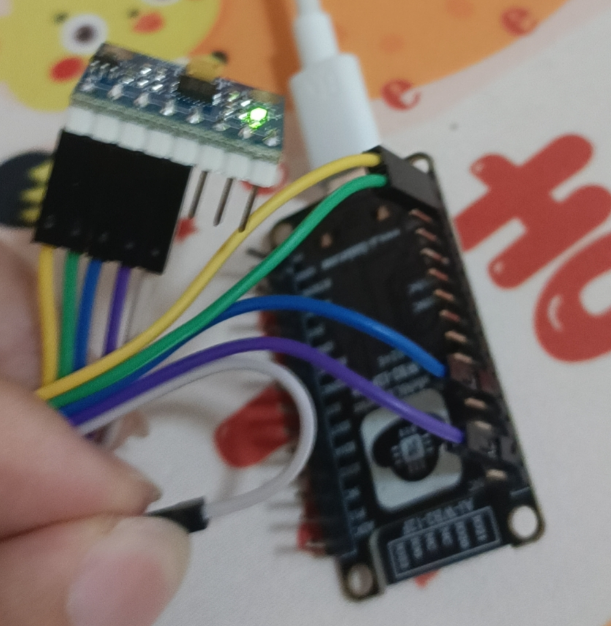
The mpu6050 communicates over iic; for iic, refer to [Ai-WB2 Intermediate] I2C Communication Interface
4. Code Implementation
Based on the register introduction above, we only need to configure the registers properly at initialization, and then read the accelerometer and gyroscope register data in the task loop.
The main initialization process is as follows:
Click to expand full code
uint8_t

mpu6050_basic_init
(
mpu6050_address_t
 addr_pin)

{

uint8_t
 res;

/* link interface function */

DRIVER_MPU6050_LINK_INIT
(&gs_handle,
mpu6050_handle_t
);

DRIVER_MPU6050_LINK_IIC_INIT
(&gs_handle, mpu6050_interface_iic_init);

DRIVER_MPU6050_LINK_IIC_DEINIT
(&gs_handle, mpu6050_interface_iic_deinit);

DRIVER_MPU6050_LINK_IIC_READ
(&gs_handle, mpu6050_interface_iic_read);

DRIVER_MPU6050_LINK_IIC_WRITE
(&gs_handle, mpu6050_interface_iic_write);

DRIVER_MPU6050_LINK_DELAY_MS
(&gs_handle, mpu6050_interface_delay_ms);

DRIVER_MPU6050_LINK_DEBUG_PRINT
(&gs_handle, mpu6050_interface_debug_print);

DRIVER_MPU6050_LINK_RECEIVE_CALLBACK
(&gs_handle, mpu6050_interface_receive_callback);

/* set the addr pin */

    res =
mpu6050_set_addr_pin
(&gs_handle, addr_pin);

if
 (res !=
0
)
    {

mpu6050_interface_debug_print
(
"mpu6050: set addr pin failed.\n"
);

return

1
;
    }

/* init */

    res =
mpu6050_init
(&gs_handle);

if
 (res !=
0
)
    {

mpu6050_interface_debug_print
(
"mpu6050: init failed.\n"
);

return

1
;
    }

/* delay 100 ms */

mpu6050_interface_delay_ms
(
100
);

/* disable sleep */

    res =
mpu6050_set_sleep
(&gs_handle, MPU6050_BOOL_FALSE);

if
 (res !=
0
)
    {

mpu6050_interface_debug_print
(
"mpu6050: set sleep failed.\n"
);
        (
void
)
mpu6050_deinit
(&gs_handle);

return

1
;
    }

/* set the default clock source */

    res =
mpu6050_set_clock_source
(&gs_handle, MPU6050_BASIC_DEFAULT_CLOCK_SOURCE);

if
 (res !=
0
)
    {

mpu6050_interface_debug_print
(
"mpu6050: set clock source failed.\n"
);
        (
void
)
mpu6050_deinit
(&gs_handle);

return

1
;
    }

/* set the default rate */

    res =
mpu6050_set_sample_rate_divider
(&gs_handle,
1000
 / (MPU6050_BASIC_DEFAULT_RATE -
1
));

if
 (res !=
0
)
    {

mpu6050_interface_debug_print
(
"mpu6050: set sample rate divider failed.\n"
);
        (
void
)
mpu6050_deinit
(&gs_handle);

return

1
;
    }

/* set the default low pass filter */

    res =
mpu6050_set_low_pass_filter
(&gs_handle, MPU6050_BASIC_DEFAULT_LOW_PASS_FILTER);

if
 (res !=
0
)
    {

mpu6050_interface_debug_print
(
"mpu6050: set low pass filter failed.\n"
);
        (
void
)
mpu6050_deinit
(&gs_handle);

return

1
;
    }

/* enable temperature sensor */

    res =
mpu6050_set_temperature_sensor
(&gs_handle, MPU6050_BOOL_TRUE);

if
 (res !=
0
)
    {

mpu6050_interface_debug_print
(
"mpu6050: set temperature sensor failed.\n"
);
        (
void
)
mpu6050_deinit
(&gs_handle);

return

1
;
    }

/* set the default cycle wake up */

    res =
mpu6050_set_cycle_wake_up
(&gs_handle, MPU6050_BASIC_DEFAULT_CYCLE_WAKE_UP);

if
 (res !=
0
)
    {

mpu6050_interface_debug_print
(
"mpu6050: set cycle wake up failed.\n"
);
        (
void
)
mpu6050_deinit
(&gs_handle);

return

1
;
    }

/* set the default wake up frequency */

    res =
mpu6050_set_wake_up_frequency
(&gs_handle, MPU6050_BASIC_DEFAULT_WAKE_UP_FREQUENCY);

if
 (res !=
0
)
    {

mpu6050_interface_debug_print
(
"mpu6050: set wake up frequency failed.\n"
);
        (
void
)
mpu6050_deinit
(&gs_handle);

return

1
;
    }

/* enable acc x */

    res =
mpu6050_set_standby_mode
(&gs_handle, MPU6050_SOURCE_ACC_X, MPU6050_BOOL_FALSE);

if
 (res !=
0
)
    {

mpu6050_interface_debug_print
(
"mpu6050: set standby mode failed.\n"
);
        (
void
)
mpu6050_deinit
(&gs_handle);

return

1
;
    }

/* enable acc y */

    res =
mpu6050_set_standby_mode
(&gs_handle, MPU6050_SOURCE_ACC_Y, MPU6050_BOOL_FALSE);

if
 (res !=
0
)
    {

mpu6050_interface_debug_print
(
"mpu6050: set standby mode failed.\n"
);
        (
void
)
mpu6050_deinit
(&gs_handle);

return

1
;
    }

/* enable acc z */

    res =
mpu6050_set_standby_mode
(&gs_handle, MPU6050_SOURCE_ACC_Z, MPU6050_BOOL_FALSE);

if
 (res !=
0
)
    {

mpu6050_interface_debug_print
(
"mpu6050: set standby mode failed.\n"
);
        (
void
)
mpu6050_deinit
(&gs_handle);

return

1
;
    }

/* enable gyro x */

    res =
mpu6050_set_standby_mode
(&gs_handle, MPU6050_SOURCE_GYRO_X, MPU6050_BOOL_FALSE);

if
 (res !=
0
)
    {

mpu6050_interface_debug_print
(
"mpu6050: set standby mode failed.\n"
);
        (
void
)
mpu6050_deinit
(&gs_handle);

return

1
;
    }

/* enable gyro y */

    res =
mpu6050_set_standby_mode
(&gs_handle, MPU6050_SOURCE_GYRO_Y, MPU6050_BOOL_FALSE);

if
 (res !=
0
)
    {

mpu6050_interface_debug_print
(
"mpu6050: set standby mode failed.\n"
);
        (
void
)
mpu6050_deinit
(&gs_handle);

return

1
;
    }

/* enable gyro z */

    res =
mpu6050_set_standby_mode
(&gs_handle, MPU6050_SOURCE_GYRO_Z, MPU6050_BOOL_FALSE);

if
 (res !=
0
)
    {

mpu6050_interface_debug_print
(
"mpu6050: set standby mode failed.\n"
);
        (
void
)
mpu6050_deinit
(&gs_handle);

return

1
;
    }

/* disable gyroscope x test */

    res =
mpu6050_set_gyroscope_test
(&gs_handle, MPU6050_AXIS_X, MPU6050_BOOL_FALSE);

if
 (res !=
0
)
    {

mpu6050_interface_debug_print
(
"mpu6050: set gyroscope test failed.\n"
);
        (
void
)
mpu6050_deinit
(&gs_handle);

return

1
;
    }

/* disable gyroscope y test */

    res =
mpu6050_set_gyroscope_test
(&gs_handle, MPU6050_AXIS_Y, MPU6050_BOOL_FALSE);

if
 (res !=
0
)
    {

mpu6050_interface_debug_print
(
"mpu6050: set gyroscope test failed.\n"
);
        (
void
)
mpu6050_deinit
(&gs_handle);

return

1
;
    }

/* disable gyroscope z test */

    res =
mpu6050_set_gyroscope_test
(&gs_handle, MPU6050_AXIS_Z, MPU6050_BOOL_FALSE);

if
 (res !=
0
)
    {

mpu6050_interface_debug_print
(
"mpu6050: set gyroscope test failed.\n"
);
        (
void
)
mpu6050_deinit
(&gs_handle);

return

1
;
    }

/* disable accelerometer x test */

    res =
mpu6050_set_accelerometer_test
(&gs_handle, MPU6050_AXIS_X, MPU6050_BOOL_FALSE);

if
 (res !=
0
)
    {

mpu6050_interface_debug_print
(
"mpu6050: set accelerometer test failed.\n"
);
        (
void
)
mpu6050_deinit
(&gs_handle);

return

1
;
    }

/* disable accelerometer y test */

    res =
mpu6050_set_accelerometer_test
(&gs_handle, MPU6050_AXIS_Y, MPU6050_BOOL_FALSE);

if
 (res !=
0
)
    {

mpu6050_interface_debug_print
(
"mpu6050: set accelerometer test failed.\n"
);
        (
void
)
mpu6050_deinit
(&gs_handle);

return

1
;
    }

/* disable accelerometer z test */

    res =
mpu6050_set_accelerometer_test
(&gs_handle, MPU6050_AXIS_Z, MPU6050_BOOL_FALSE);

if
 (res !=
0
)
    {

mpu6050_interface_debug_print
(
"mpu6050: set accelerometer test failed.\n"
);
        (
void
)
mpu6050_deinit
(&gs_handle);

return

1
;
    }

/* disable fifo */

    res =
mpu6050_set_fifo
(&gs_handle, MPU6050_BOOL_FALSE);

if
 (res !=
0
)
    {

mpu6050_interface_debug_print
(
"mpu6050: set fifo failed.\n"
);
        (
void
)
mpu6050_deinit
(&gs_handle);

return

1
;
    }

/* disable temp fifo */

    res =
mpu6050_set_fifo_enable
(&gs_handle, MPU6050_FIFO_TEMP, MPU6050_BOOL_FALSE);

if
 (res !=
0
)
    {

mpu6050_interface_debug_print
(
"mpu6050: set fifo enable failed.\n"
);
        (
void
)
mpu6050_deinit
(&gs_handle);

return

1
;
    }

/* disable xg fifo */

    res =
mpu6050_set_fifo_enable
(&gs_handle, MPU6050_FIFO_XG, MPU6050_BOOL_FALSE);

if
 (res !=
0
)
    {

mpu6050_interface_debug_print
(
"mpu6050: set fifo enable failed.\n"
);
        (
void
)
mpu6050_deinit
(&gs_handle);

return

1
;
    }

/* disable yg fifo */

    res =
mpu6050_set_fifo_enable
(&gs_handle, MPU6050_FIFO_YG, MPU6050_BOOL_FALSE);

if
 (res !=
0
)
    {

mpu6050_interface_debug_print
(
"mpu6050: set fifo enable failed.\n"
);
        (
void
)
mpu6050_deinit
(&gs_handle);

return

1
;
    }

/* disable zg fifo */

    res =
mpu6050_set_fifo_enable
(&gs_handle, MPU6050_FIFO_ZG, MPU6050_BOOL_FALSE);

if
 (res !=
0
)
    {

mpu6050_interface_debug_print
(
"mpu6050: set fifo enable failed.\n"
);
        (
void
)
mpu6050_deinit
(&gs_handle);

return

1
;
    }

/* disable accel fifo */

    res =
mpu6050_set_fifo_enable
(&gs_handle, MPU6050_FIFO_ACCEL, MPU6050_BOOL_FALSE);

if
 (res !=
0
)
    {

mpu6050_interface_debug_print
(
"mpu6050: set fifo enable failed.\n"
);
        (
void
)
mpu6050_deinit
(&gs_handle);

return

1
;
    }

/* set the default interrupt level */

    res =
mpu6050_set_interrupt_level
(&gs_handle, MPU6050_BASIC_DEFAULT_INTERRUPT_PIN_LEVEL);

if
 (res !=
0
)
    {

mpu6050_interface_debug_print
(
"mpu6050: set interrupt level failed.\n"
);
        (
void
)
mpu6050_deinit
(&gs_handle);

return

1
;
    }

/* set the default pin type */

    res =
mpu6050_set_interrupt_pin_type
(&gs_handle, MPU6050_BASIC_DEFAULT_INTERRUPT_PIN_TYPE);

if
 (res !=
0
)
    {

mpu6050_interface_debug_print
(
"mpu6050: set interrupt pin type failed.\n"
);
        (
void
)
mpu6050_deinit
(&gs_handle);

return

1
;
    }

/* set the default motion interrupt */

    res =
mpu6050_set_interrupt
(&gs_handle, MPU6050_INTERRUPT_MOTION, MPU6050_BASIC_DEFAULT_INTERRUPT_MOTION);

if
 (res !=
0
)
    {

mpu6050_interface_debug_print
(
"mpu6050: set interrupt failed.\n"
);
        (
void
)
mpu6050_deinit
(&gs_handle);

return

1
;
    }

/* set the default fifo overflow interrupt */

    res =
mpu6050_set_interrupt
(&gs_handle, MPU6050_INTERRUPT_FIFO_OVERFLOW, MPU6050_BASIC_DEFAULT_INTERRUPT_FIFO_OVERFLOW);

if
 (res !=
0
)
    {

mpu6050_interface_debug_print
(
"mpu6050: set interrupt failed.\n"
);
        (
void
)
mpu6050_deinit
(&gs_handle);

return

1
;
    }

/* set the default dmp interrupt */

    res =
mpu6050_set_interrupt
(&gs_handle, MPU6050_INTERRUPT_DMP, MPU6050_BASIC_DEFAULT_INTERRUPT_DMP);

if
 (res !=
0
)
    {

mpu6050_interface_debug_print
(
"mpu6050: set interrupt failed.\n"
);
        (
void
)
mpu6050_deinit
(&gs_handle);

return

1
;
    }

/* set the default i2c master interrupt */

    res =
mpu6050_set_interrupt
(&gs_handle, MPU6050_INTERRUPT_I2C_MAST, MPU6050_BASIC_DEFAULT_INTERRUPT_I2C_MAST);

if
 (res !=
0
)
    {

mpu6050_interface_debug_print
(
"mpu6050: set interrupt failed.\n"
);
        (
void
)
mpu6050_deinit
(&gs_handle);

return

1
;
    }

/* set the default data ready interrupt */

    res =
mpu6050_set_interrupt
(&gs_handle, MPU6050_INTERRUPT_DATA_READY, MPU6050_BASIC_DEFAULT_INTERRUPT_DATA_READY);

if
 (res !=
0
)
    {

mpu6050_interface_debug_print
(
"mpu6050: set interrupt failed.\n"
);
        (
void
)
mpu6050_deinit
(&gs_handle);

return

1
;
    }

/* set the default interrupt latch */

    res =
mpu6050_set_interrupt_latch
(&gs_handle, MPU6050_BASIC_DEFAULT_INTERRUPT_LATCH);

if
 (res !=
0
)
    {

mpu6050_interface_debug_print
(
"mpu6050: set interrupt latch failed.\n"
);
        (
void
)
mpu6050_deinit
(&gs_handle);

return

1
;
    }

/* set the default interrupt read clear */

    res =
mpu6050_set_interrupt_read_clear
(&gs_handle, MPU6050_BASIC_DEFAULT_INTERRUPT_READ_CLEAR);

if
 (res !=
0
)
    {

mpu6050_interface_debug_print
(
"mpu6050: set interrupt read clear failed.\n"
);
        (
void
)
mpu6050_deinit
(&gs_handle);

return

1
;
    }

/* set the extern sync */

    res =
mpu6050_set_extern_sync
(&gs_handle, MPU6050_BASIC_DEFAULT_EXTERN_SYNC);

if
 (res !=
0
)
    {

mpu6050_interface_debug_print
(
"mpu6050: set extern sync failed.\n"
);
        (
void
)
mpu6050_deinit
(&gs_handle);

return

1
;
    }

/* set the default fsync interrupt */

    res =
mpu6050_set_fsync_interrupt
(&gs_handle, MPU6050_BASIC_DEFAULT_FSYNC_INTERRUPT);

if
 (res !=
0
)
    {

mpu6050_interface_debug_print
(
"mpu6050: set fsync interrupt failed.\n"
);
        (
void
)
mpu6050_deinit
(&gs_handle);

return

1
;
    }

/* set the default fsync interrupt level */

    res =
mpu6050_set_fsync_interrupt_level
(&gs_handle, MPU6050_BASIC_DEFAULT_FSYNC_INTERRUPT_LEVEL);

if
 (res !=
0
)
    {

mpu6050_interface_debug_print
(
"mpu6050: set fsync interrupt level failed.\n"
);
        (
void
)
mpu6050_deinit
(&gs_handle);

return

1
;
    }

/* set the default iic master */

    res =
mpu6050_set_iic_master
(&gs_handle, MPU6050_BASIC_DEFAULT_IIC_MASTER);

if
 (res !=
0
)
    {

mpu6050_interface_debug_print
(
"mpu6050: set iic master failed.\n"
);
        (
void
)
mpu6050_deinit
(&gs_handle);

return

1
;
    }

/* set the default iic bypass */

    res =
mpu6050_set_iic_bypass
(&gs_handle, MPU6050_BASIC_DEFAULT_IIC_BYPASS);

if
 (res !=
0
)
    {

mpu6050_interface_debug_print
(
"mpu6050: set iic bypass failed.\n"
);
        (
void
)
mpu6050_deinit
(&gs_handle);

return

1
;
    }

/* set the default accelerometer range */

    res =
mpu6050_set_accelerometer_range
(&gs_handle, MPU6050_BASIC_DEFAULT_ACCELEROMETER_RANGE);

if
 (res !=
0
)
    {

mpu6050_interface_debug_print
(
"mpu6050: set accelerometer range failed.\n"
);
        (
void
)
mpu6050_deinit
(&gs_handle);

return

1
;
    }

/* set the default gyroscope range */

    res =
mpu6050_set_gyroscope_range
(&gs_handle, MPU6050_BASIC_DEFAULT_GYROSCOPE_RANGE);

if
 (res !=
0
)
    {

mpu6050_interface_debug_print
(
"mpu6050: set gyroscope range failed.\n"
);
        (
void
)
mpu6050_deinit
(&gs_handle);

return

1
;
    }

return

0
;
}
After initialization, you only need to read the register values in the task loop.
Click to expand full code
uint8_t

mpu6050_basic_read
(
float
 g[
3
],
float
 dps[
3
])

{

uint16_t
 len;

int16_t
 accel_raw[
3
];

int16_t
 gyro_raw[
3
];

float
 accel[
3
];

float
 gyro[
3
];

/* set 1 */

    len =
1
;

/* read data */

if
 (
mpu6050_read
(&gs_handle,
                    (
int16_t
 (*)[
3
])&accel_raw, (
float
 (*)[
3
])&accel,
                    (
int16_t
 (*)[
3
])&gyro_raw, (
float
 (*)[
3
])&gyro,
                     &len) !=
0

                    )
    {

return

1
;
    }

/* copy the data */

    g[
0
] = accel[
0
];
    g[
1
] = accel[
1
];
    g[
2
] = accel[
2
];
    dps[
0
] = gyro[
0
];
    dps[
1
] = gyro[
1
];
    dps[
2
] = gyro[
2
];

return

0
;
}
For the complete project, refer to Ai-Thinker-WB2/applications/iot-solution/demo_mpu6050/demo_mpu6050.
5. Flashing and Verification

At this point, the accelerometer and gyroscope data can be read directly.