

Overview
PWM (Pulse Width Modulation) controls the average level by adjusting the duty cycle of an output square wave; it's the foundation for LED dimming, buzzers, and motor speed control. This tutorial uses the official example three-channel PWM driving an RGB LED: red, green, and blue channels each output waveforms with different duty cycles.
In plain words: PWM is like a hand rapidly switching a light on and off — on longer, off shorter, the light appears brighter; the reverse, dimmer. The "fraction of time the light is on" is the duty cycle (50% duty = on half the time, off half the time). Because the switching is faster than the eye can follow, the light just looks steadily bright or dim.
This tutorial is based on the official Ai-Thinker SDK (Ai-Thinker-Open/Ai-Thinker-WB2, version
release_bl_iot_sdk_1.6.40) exampleapplications/peripherals/demo_pwm; the code can be found directly in your local SDK.
Wire per the official example (see SDK applications/peripherals/demo_pwm/README.md):
| Ai-WB2 Pin | RGB LED Pin |
|---|---|
| IO14 | Red |
| IO17 | Green |
| IO3 | Blue |
| 3V3 | VCC |
| GND | GND |
💡 The example multiplexes the three GPIOs as PWM (multiplexing = one pin can switch between different functions;
gpioFun = 8selects the PWM function). The same pin can’t be used for ordinary GPIO output at the same time.
Open a terminal and enter the official demo_pwm example project directory:
cd ~/Ai-Thinker-WB2/applications/peripherals/demo_pwm
Note:
cdis the “change directory” command; this enters the demo_pwm example project. All subsequentmakebuild andmake flashcommands must run inside this directory first.
Open demo_pwm/main.c. The full code for this step has been moved to the end of this page:
📜 Full Code — in the “Full Code” section below, collapsed by default — click to expand, identical to the official example (
applications/peripherals/demo_pwm/demo_pwm/main.c).
Code highlights:
| Code | Purpose |
|---|---|
GLB_GPIO_Cfg_Type cfg[] |
Configure the GPIOs as PWM: gpioPin picks the pin, gpioFun = 8 picks the multiplexed function; wrong pin or function number means no waveform |
GLB_GPIO_Init(cfg + i) |
Initialize the three GPIO multiplexing configs; without it the pins stay ordinary GPIO and produce no waveform |
PWM_Smart_Configure2(ch, clkDiv, period, threshold2) |
Configure the PWM channel: frequency = 80MHz ÷ Divider ÷ Period, duty cycle = threshold2 ÷ Period; wrong math means the LED doesn’t light or the brightness is off |
PWM_Channel_Enable(ch) |
Enable the PWM channel to start outputting; without it the pin stays low forever and the LED doesn’t light |
Three-channel PWM output parameters:
| Channel | Pin | Duty Cycle | Frequency |
|---|---|---|---|
| 2 | IO14 (red) | 50% (1/2) | 40MHz |
| 3 | IO17 (green) | 75% (6/8) | 5MHz |
| 4 | IO3 (blue) | 10% (1/10) | 1MHz |
Build in the project directory:
make -j8
Note:
makeis the “build” command, turning code into firmware (a program file) the board can run;-j8builds with 8 parallel cores, faster.
On success a firmware build_out/demo_pwm.bin is generated.
Keep the board connected via USB, confirm the serial device, and flash:
make flash p=/dev/ttyUSB0 b=921600
Note:
make flashis the “flash” command, writing the compiled firmware into the board’s chip. Afterp=comes the serial device (change it to your computer’s actual port — check withls /dev/ttyUSB*);b=is the flash baud rate (transfer speed).
⏳ During flashing, press and hold the EN button on the board when prompted to enter download mode; wait for the progress bar to complete — that means the flash succeeded.
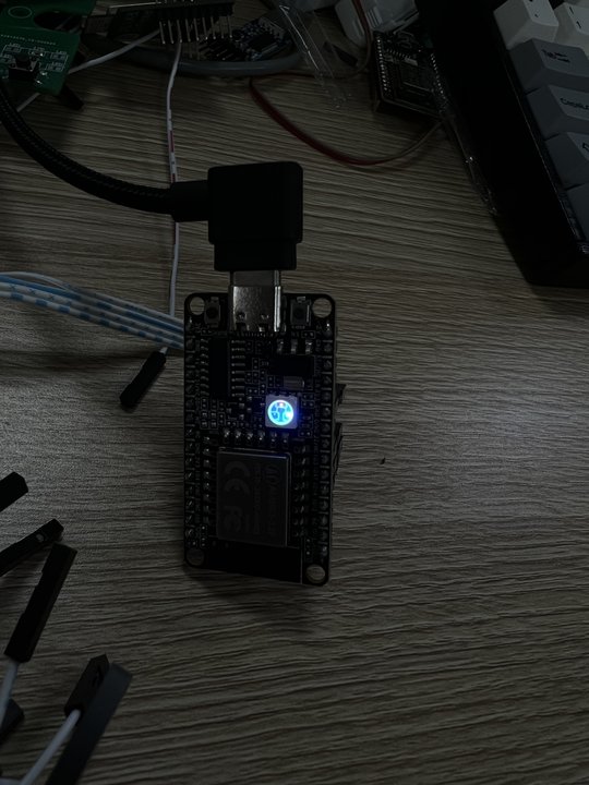
After flashing, the board automatically restarts; the RGB LED’s three color dies light at their own duty cycles, showing a mixed color overall; a logic analyzer shows three square waves with different frequencies and duty cycles (see the official example img/logic_analyzer.jpg).
💡 Set a channel’s
threshold2to 1/2 ofperiodfor a 50% duty cycle; set it to0for constant low. After modifying, re-runmake -j8 && make flashto verify.
Seeing all three color dies lit at the same time with different brightness (mixed color) means success; if a die doesn’t light or the color is wrong, check the “FAQ & Troubleshooting” section at the end.
API Summary for This Tutorial
GLB_GPIO_Init(cfg)
Multiplexes the specified pins to peripheral functions such as PWM output (configuring three GPIOs as PWM in this tutorial).
Parameters:
cfg:GLB_GPIO_Cfg_Typestruct pointer, required. Key fields:gpioPin(pin number, values:GPIO_PIN_0~GPIO_PIN_22, must be a PWM-capable pin),gpioFun(multiplexed function number, values:GPIO_FUN_PWM0~GPIO_FUN_PWM5,8here),gpioMode(direction mode,GPIO_MODE_OUTPUThere),pullType(pull resistors,GPIO_PULL_DOWNhere)
Return: none
PWM_Channel_Enable(ch)
Turns on a PWM channel to start outputting the configured waveform.
Parameters:
ch: PWM channel number, values:PWM_CH0~PWM_CH5(must correspond to the GPIO multiplexed function, e.g.PWM_CH0↔GPIO_FUN_PWM0)
Return: none
PWM_Channel_Disable(ch)
Stops PWM output (the pin returns to a static level).
Parameters:
ch: PWM channel number, values:PWM_CH0~PWM_CH5
Return: none
PWM_Smart_Configure2(ch, clkDiv, period, threshold2)
Sets the divider, period and threshold to determine the output frequency and duty cycle (a custom wrapper in the example, derived from the official PWM_Smart_Configure).
Parameters:
ch: PWM channel number, values:PWM_CH0~PWM_CH5clkDiv: clock divider, values:1~255(frequency = 80MHz ÷ Divider ÷ Period)period: period count (determines frequency), values:1~0xFFFF, e.g.4000(duty cycle denominator)threshold2: threshold 2 (determines duty cycle), values:0~period, duty cycle = threshold2 ÷ period, e.g.2000(50% duty)
Return: none
Full Code
Below is the complete demo_pwm/main.c source, identical to the official example (applications/peripherals/demo_pwm/demo_pwm/main.c):
📜 Click to expand the full demo_pwm/main.c code
#include <FreeRTOS.h>
#include <task.h>
#include <blog.h>
#include <bl602.h>
#include <bl602_gpio.h>
#include <bl602_glb.h>
#include <bl_pwm.h>

#define PWM_Get_Channel_Reg(ch)  (PWM_BASE+PWM_CHANNEL_OFFSET+(ch)*0x20)
#define PWM_STOP_TIMEOUT_COUNT          (160*1000)

/// @brief Copy from PWM_Smart_Configure. Use Bus Clock instead of External Crystal Clock for PWM Timer
/// @param ch PWM Channel
/// @param clkDiv PWM clock divider
/// @param period PWM period
/// @param threshold2
/// @return
BL_Err_Type PWM_Smart_Configure2(PWM_CH_ID_Type ch, uint16_t clkDiv, uint16_t period,uint16_t threshold2)
{
    uint32_t tmpVal;
    uint32_t timeoutCnt = PWM_STOP_TIMEOUT_COUNT;
    /* Get channel register */
    uint32_t PWMx = PWM_Get_Channel_Reg(ch);

    tmpVal = BL_RD_REG(PWMx, PWM_CONFIG);
    // if(BL_GET_REG_BITS_VAL(tmpVal, PWM_REG_CLK_SEL) != PWM_CLK_XCLK){
    if(BL_GET_REG_BITS_VAL(tmpVal, PWM_REG_CLK_SEL) != PWM_CLK_BCLK){
        BL_WR_REG(PWMx, PWM_CONFIG, BL_SET_REG_BIT(tmpVal, PWM_STOP_EN));
        while(!BL_IS_REG_BIT_SET(BL_RD_REG(PWMx, PWM_CONFIG), PWM_STS_TOP)){
            timeoutCnt--;
            if(timeoutCnt == 0){
                return TIMEOUT;
            }
        }
        // tmpVal = BL_SET_REG_BITS_VAL(tmpVal, PWM_REG_CLK_SEL, PWM_CLK_XCLK);
        tmpVal = BL_SET_REG_BITS_VAL(tmpVal, PWM_REG_CLK_SEL, PWM_CLK_BCLK);
    }
    tmpVal = BL_SET_REG_BITS_VAL(tmpVal, PWM_OUT_INV, PWM_POL_NORMAL);
    tmpVal = BL_SET_REG_BITS_VAL(tmpVal, PWM_STOP_MODE, PWM_STOP_GRACEFUL);
    BL_WR_REG(PWMx, PWM_CONFIG, tmpVal);

    /* Config pwm division */
    BL_WR_REG(PWMx, PWM_CLKDIV, clkDiv);

    /* Config pwm period and duty */
    BL_WR_REG(PWMx, PWM_PERIOD, period);
    BL_WR_REG(PWMx, PWM_THRE1, 0);
    BL_WR_REG(PWMx, PWM_THRE2, threshold2);

    return SUCCESS;
}

int main(void)
{
    GLB_GPIO_Cfg_Type cfg[3] = {
        {
            .drive = 0,
            .smtCtrl = 1,
            .gpioMode = GPIO_MODE_OUTPUT,
            .pullType = GPIO_PULL_DOWN,
            .gpioPin = 14,  /// red
            .gpioFun = 8,
        },
        {
            .drive = 0,
            .smtCtrl = 1,
            .gpioMode = GPIO_MODE_OUTPUT,
            .pullType = GPIO_PULL_DOWN,
            .gpioPin = 17,  /// green
            .gpioFun = 8,
        },
        {
            .drive = 0,
            .smtCtrl = 1,
            .gpioMode = GPIO_MODE_OUTPUT,
            .pullType = GPIO_PULL_DOWN,
            .gpioPin = 3,  /// blue
            .gpioFun = 8,
        },
    };

    for (int i = 0; i < 3; i++) {
        GLB_GPIO_Init(cfg + i);

        PWM_CH_ID_Type ch = cfg[i].gpioPin % PWM_CH_MAX;
        PWM_Channel_Disable(ch);
    }

    /// PWM Frequency = 80 Hz / Divider / Period

    /// set pwm channel 2 for 50% duty, 40MHz
    /// Divider = 1
    /// Period = 2
    PWM_Smart_Configure2(2, 1, 2, 1);
    PWM_Channel_Enable(2);

    /// set pwm channel 3 for 75% duty, 5MHz
    /// Divider = 2
    /// Period = 8
    PWM_Smart_Configure2(3, 2, 8, 6);
    PWM_Channel_Enable(3);

    /// set pwm channel 3 for 10% duty, 1MHz
    /// Divider = 8
    /// Period = 10
    PWM_Smart_Configure2(4, 8, 10, 1);
    PWM_Channel_Enable(4);

    for (;;) {
        vTaskDelay(pdMS_TO_TICKS(1000));
    }

    return 0;
}
FAQ & Troubleshooting
⚠️ RGB LED doesn't light or colors are wrong
Cause: the RGB LED module's pin order doesn't match the example, or the common-anode/common-cathode type mismatches
Fix: confirm against the module silkscreen that R/G/B connect to IO14/IO17/IO3 respectively; for common-anode LEDs, invert PWM_OUT_INV or swap 3V3/GND
⚠️ Using a pin as GPIO first then PWM doesn't take effect
Cause: the pin's multiplexed function wasn't switched cleanly
Fix: power cycle or reset before flashing again; confirm gpioFun = 8 is the PWM multiplexed function number (see the SDK pin multiplexing table)
⚠️ The duty cycle formula is easy to get backwards
Cause: the roles of threshold2 and Period get confused
Fix: duty cycle = threshold2 / Period; e.g. Period=10, threshold2=1 gives 10% duty
⚠️ Flashing keeps waiting, the progress bar doesn't move
Cause: download mode wasn't entered, or the cable only charges and can't transfer data
Fix: press and hold EN to enter download mode when prompted; try a Type-C cable that can transfer data and retry
⚠️ Serial device not found or permission denied
Cause: /dev/ttyUSB0 doesn't exist or permissions are insufficient on Linux; USB-to-serial driver not installed on Windows
Fix: on Linux confirm the device with ls /dev/ttyUSB*, for permissions run sudo usermod -aG dialout $USER then log in again; on Windows install the driver in Device Manager and confirm the COM number
⚠️ Running make reports no Makefile found
Cause: the build command ran in the wrong directory (it must run inside the example project)
Fix: first cd ~/Ai-Thinker-WB2/applications/peripherals/demo_pwm into the project directory, then run make -j8
Self-Check
The RGB LED's three colors light simultaneously with different brightness (mixed color), or a logic analyzer shows three square waves with different frequencies — PWM is verified.