LORAWAN system usage tutorial
LORAWAN system usage tutorial
This tutorial is mainly to guide customers how to use the LORAWAN system, which includes at least the following parts:

1. A gateway (RHF2S008P4G)
2. At least one node module SX127x-052
3.NetServer Cloud
4. Customer private cloud
5. Mobile APP or front end
This tutorial NetServer cloud uses LORIOT (https://www.loriot.io/login.html), this NetServer cloud supports global deployment, and 10 terminal devices are free to try
Preparation before use:
1. Register an account in the backend of LORIOT Cloud ([[http://cn1.loriot.io |LORIOT Cloud Registration Address]] ).
2. LoRaWAN node module is connected to the serial port, the connection method is as follows:
LoRaWAN node module Serial port module
    VCC------------3.3V
    GND------------GND
  USART_RX-------USART_TX
  USART_TX-------USART_RX
  {{:lora:spec:loriot registration.png?300|}}
3. Install the gateway. Please refer to the documentation for the specific connection method of the gateway.
Gateway installation document ==== The following specific operation steps are listed to realize the sub-node module uploading data to the LORIOT cloud.
====
Gateway RHF2S008 configuration
1.ssh login gateway RHF2S008P4G
The default login user information is as follows:
Username: rxhf
Password: risinghf
Connect the RHF2S008P4G device to the DHCP router, log in to the router or take an IP scan to find the IP of the RHF2S008P4G device. The host name of the RHF2S008P4G device is “rhf2s008”.
After obtaining the IP, the user can log in to the device through SSH to view the configuration or set the parameters. Common Windows tools include PuTTY, TeraTerm. Linux users can log in directly with the SSH tool. The SSH port number is the default value 22.
For example, the following methods can be used to log in to the RHF2S008P4G device with IP 192.168.1.221 on the Windows/Linux platform respectively Windows:
Linux
ssh rxhf@192.168.1.221
2. Log in to the LORIOT backstage, [[https://www.loriot.io/login.html|LORIOT login address]], and register the gateway device to the platform.
1) Get the MAC address, the format is xx:xx:xx:xx:xx:xx. The MAC address is usually posted on the side of the host.
2) Visit http://cn1.loriot.io to register an account, users who have registered accounts please log in directly
3) Go to Dashboard → Gateways → Add Gateway, select RHF2S008 platform
4). Radio front-end option selection, matching the selected gateway model to register the device. The options are:
A) 868/915 MHz (SX1257)
B)434/470/780 MHz (SX1255)
C) Note: RHF2S008P4G-780MHz gateway needs to select “868/915 MHz (SX1257)”
5) Continue to pull down, fill in the Mac address, and fill in the gateway location information according to the prompt information
6) Click “Register RisingHF RHF2S008 Gateway” to complete the registration
7) Click “Go to the gateway detail page” or click “gateway xx:xx:xx:xx:xx:xx” from the left console to enter the configuration page
8) The frequency scheme is selected according to the gateway channel selected by the user, generally CN434 or CN470 (depending on the actual gateway model), or other supported frequencies.
9) The gateway registration is complete
10) Connect the network cable and power on the RHF2S008. If it is powered on, please restart the device after registration is complete
11) Start testing
3. Start Loriot service
The default choice is to connect to the cn1 server, select the Loriot server area, for example, use the following command to select the ap1 server
sudo su
cd /opt/loriot/bin
ln -sf ap1 lrt
Replace ap1 with af1 ap1 au1 cn1 eu1 sa1 us1 to select different server areas.
Set boot up:
sudo systemctl enable loriot-gw
start up:
sudo systemctl start loriot-gw
stop:
sudo systemctl stop loriot-gw
Turn off startup:
sudo systemctl disable loriot-gw
Note: After the setting is set to boot, if the user needs to switch to another server, be sure to execute the stop and turn off the boot command to prevent loriot-gw from interfering with other services.
4. Configure gateway frequency
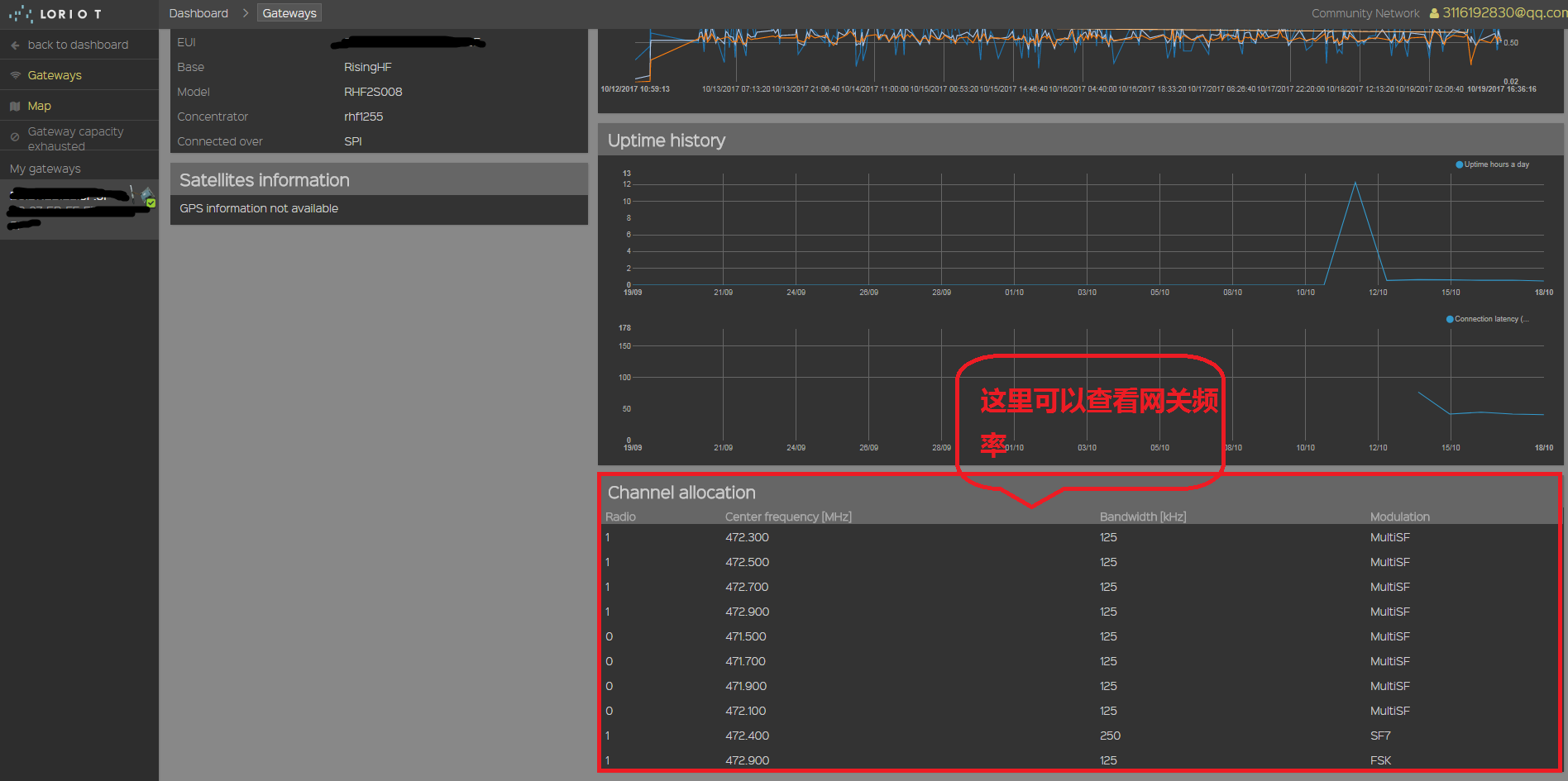
Loriot gateway configuration items are all configured in the cloud. Open the Loriot console and find the corresponding gateway page. You can select the corresponding frequency band at the Frequency plan. For specific frequency definitions, please refer to the Loriot frequency definition table online document.
https://cn1.loriot.io/home/documentation.html#docu/frequency-plan
Because the antenna presented by the gateway will be matched according to customer needs when leaving the factory, please contact our company to confirm the frequency of the gateway
5. Use gateway GPS module
RHF2S008P4G has built-in GPS module, supports GPS function, LoRaWAN Class B standard hardware.
The following commands can be used to simply test the function of the GPS module.
sudo gpsctl on
stty -F /dev/serial1 9600 -raw -echo
cat </dev/serial1
You can get information similar to the following
$GPRMC,095521.00,V,,,,,,,100417,,,N*74
$GPVTG,,,,,,,,,N*30
$GPGGA,095521.00,,,,,0,00,99.99,,,,,,*6C
$GPGSA,A,1,,,,,,,,,,,,,,99.99,99.99,99.99*30
$GPGSV,4,1,13,01,70,146,,03,09,158,,07,75,257,,08,36,031,*77
$GPGSV,4,2,13,09,15,217,,11,80,034,,16,06,101,,17,14,253,*7D
$GPGSV,4,3,13,22,17,134,,23,05,183,,27,06,051,,28,20,314,*7B
$GPGSV,4,4,13,30,41,313,*4C
$GPGLL,,,,,095521.00,V,N*40
RHF76x-052 node module configuration
RHF76x-052 has built-in LoRaWAN protocol stack and does not support secondary development. It is controlled by at command. For specific at command, please refer to RHF76x-052 command document. RHF76x-052 instruction document
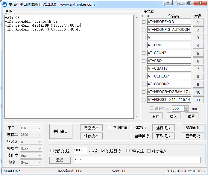
1. Connect the RHF76x-052 node to the computer serial port, open the computer serial port software, the default baud rate is 9600, 8 data bits, no parity bit, 1 stop bit, no flow control, then open the serial port and enter “at ”, if it returns “+AT: OK”, it proves that the computer can send the at command to the module.
Note that you must add a carriage return and line feed “\r\n” every time you enter the at command, otherwise the default is an input error.
2. It is recommended to restore the factory mode when the module is powered on for the first time, input “AT+FDEFAULT” in the serial port, and return “+FDEFAULT: OK” if successful, and input “at+id” “ View module id information
3. The communication between the node module and the gateway must have the same frequency. Go to the Loriot background to check the gateway frequency
Then configure the node module frequency to be consistent with the gateway frequency.
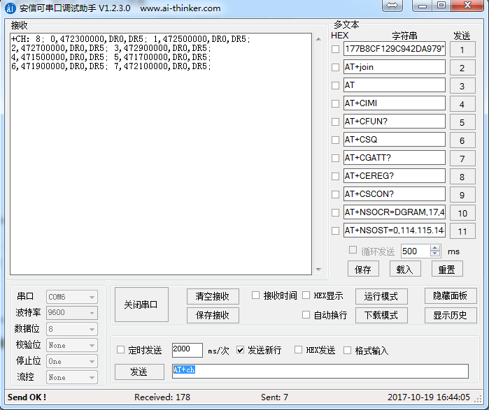
a) Enter ”AT+CH“ to view the frequency of the node module configuration
b) Input “at+ch=xx,xx” (number of channels, frequency) for frequency configuration
For example, according to the Loriot background to view the gateway frequency, enter in sequence
“AT+CH=0, 472.300”
“AT+CH=1, 472.500”
“AT+CH=2,472.700”
“AT+CH=3,472.900”
“AT+CH=4, 471.500”
“AT+CH=5, 471.700”
“AT+CH=6, 471.900”
“AT+CH=7,472.100”
If the configuration is successful each time, the current configuration frequency and channel number will be returned
e.g AT+CH=0,472.3
Return: +CH: 0,472300000,DR0:DR5
4.OTAA connects to the network and sends data
a) Each node needs to register in the background, add a device on the background page Applications→SimpleApp→Enroll new device, fill in step 2 in the Device EUI text box to get DevEui, and finally click Enroll OTAA/ABP device, then it will succeed Add equipment.
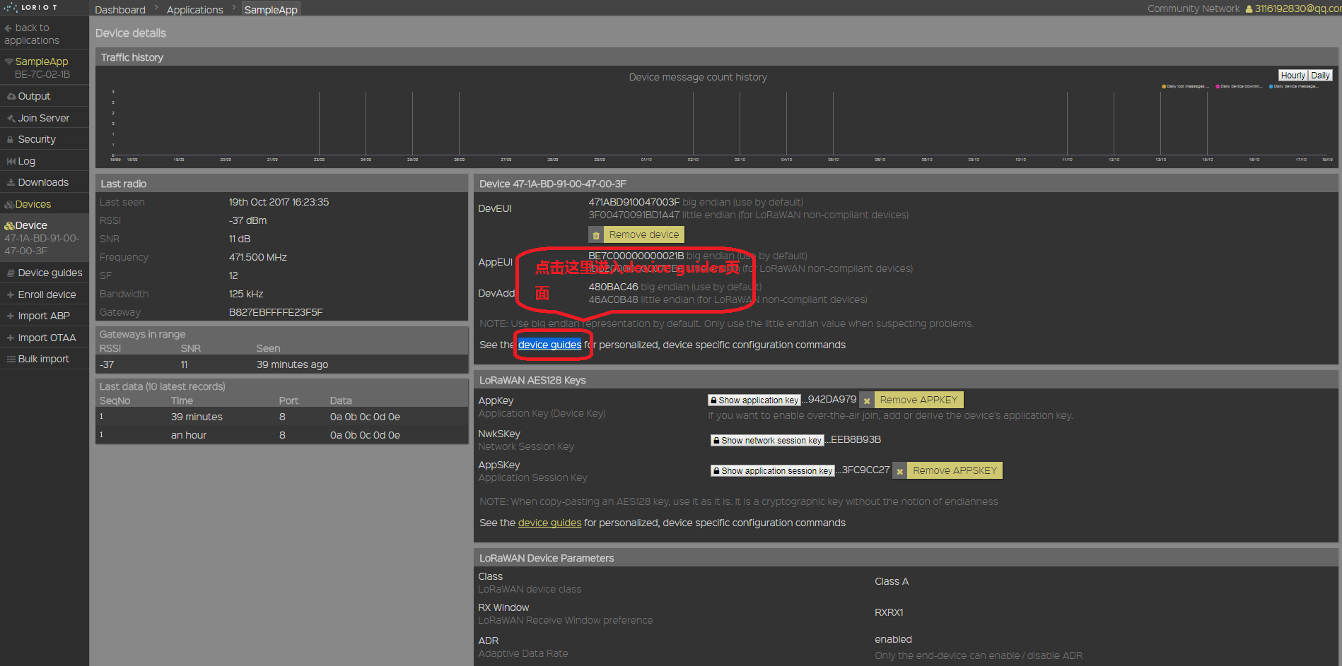
b) Select the newly added node in step a, enter the Device details page, and click the device guides page
Then select RisingHF Module / Modem, you can see the node key configuration guide, follow the web page prompts to configure DevEui, AppEui, APPKEY in sequence in the serial port.
c) The serial port sends ”at+mode=lwota“ to configure the node module's network access mode to OTAA mode.
d) The serial port sends ”at+join“ to apply for the node to join the network, if the network is successful, it will return to DevAddr
+JOIN: Starting
+JOIN: NORMAL, count 1, 0s, 0s
+JOIN: Network joined
+JOIN: NetID 4C5254 DevAddr a9:4b:5c:0a
+JOIN: Done
e) Send ”AT+CLASS=A“ through the serial port to configure CLASS A mode
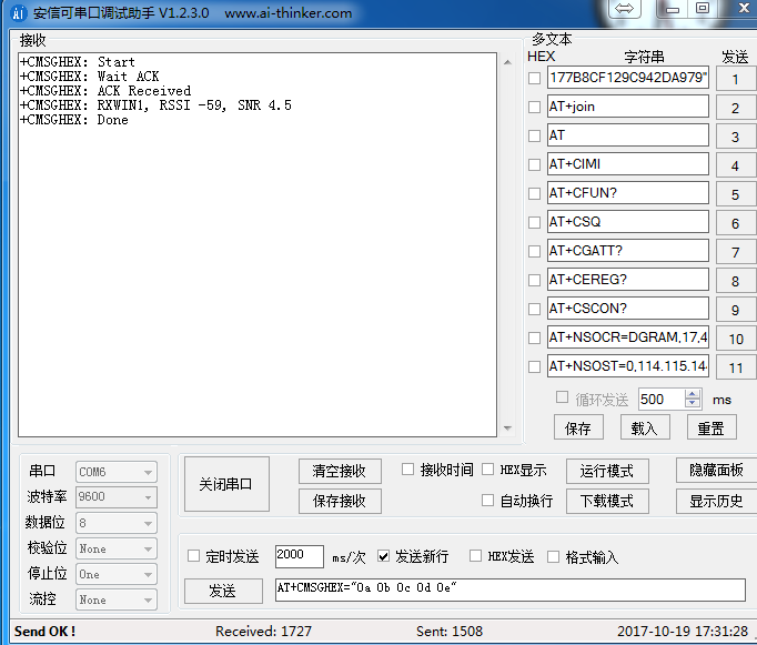
f) The serial port sends “AT+CMSGHEX=“xxxx”” to send the hexadecimal information, and if the sending is successful, the information in the figure can be returned.
5. ABP access to the network and send data
a) Each node needs to register in the background, add a device on the background page Applications→SimpleApp→Enroll new device, fill in step 2 in the Device EUI text box to get the DevEui, and finally click Enroll OTAA/ABP device, then it will succeed Add equipment.
b) Select the newly added node in step a, enter the Device details page, and click the device guides page
Then select RisingHF Module / Modem, you can see the node key configuration guide, follow the web page prompts to configure DevAddr, NWKSKEY, APPSKEY in sequence in the serial port.
c) Send ”AT+MODE=LWABP“ through the serial port to configure the node module's network access mode to ABP mode.
d)Serial port sends “AT+CMSGHEX=“xxxx”” to send hexadecimal information, if the sending is successful, you can return to the information in the picture.
Note: There must be a time interval for each transmission. After a single data is sent, ”+CMSGHEX: No band in 143638ms“ is returned, indicating that the next successful transmission can only be done after the return value time.


