Pudding series development board-A9G development board information
Pudding series development board-A9G development board information
A9G development board schematic diagram: A9G development board schematic diagram
A9G development board principle library: A9G development board principle library
For more details about GPRS, please consult: https://docs.ai-thinker.com/gprs
1. Introduction
1. Introduction to the development board
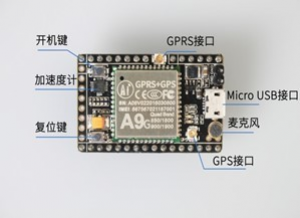
l The A9G development board is a multi-functional development board based on the A9G GPRS/GSM+GPS/BDS module. It can be used to verify the basic communication and peripheral functions of the A9G module.
l The A9G development board has basic telephone/message, GPRS network communication, GPS/BDS dual-mode positioning functions.
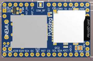
l The A9G development board is equipped with lithium battery charging management, microphone, speaker interface, USB communication interface, multiple user buttons/leds, TF card slot, acceleration sensor, SPI interface, I2C2 interface, and ADC interface.
l A9G development board camera expansion board, can be connected to an external 30W/200W camera.
l A slot machine expansion board on the A9G development board, which can be connected to a traditional slot machine.
To
Based on the above functions, A9G can be used for a variety of peripheral prototype development verification:
l Vehicle anti-theft device using GPRS+GPS and acceleration sensor.
l Remote monitoring intercom using GSM and microphone/speaker
l Smart watch using GPRS/GSM+GPS, 1.54-inch capacitive touch screen
l Elderly monitoring watch using GPRS/GSM+GPS, heart rate blood oxygen sensor, 1.54 inch capacitive touch screen
l Remote surveillance camera using GPRS+TF+ camera expansion board
l WeChat payment slot machine solution using slot machine expansion board
To
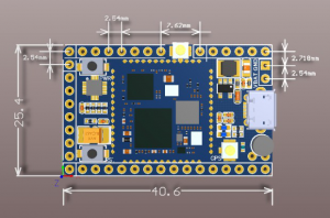
2. Development board appearance and size
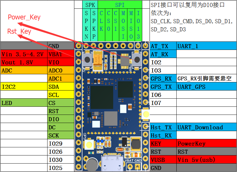
3. Pin introduction
2. How to operate
1. Basic debugging
Wiring
The development board uses AT firmware. When debugging, use 4 wires to connect usb-ttl and connect to the computer for debugging: VUSB→5V; GND→GND; AT_TX→RX; AT_RX→TX;
Or use USB for power supply, and connect three more lines GND→GND; AT_TX→RX; AT_RX→TX;
Or lithium battery power supply VBAT→(3.3v-4.2)V; GND→GND; AT_TX→RX; AT_RX→TX; (To use VBAT power supply, you need to press the power_key button for about 2s)
Power on
The A9G development board can be powered by lithium batteries or USB.
The module will run automatically after power-on for 1~2S, and the serial port will automatically output information at this time. The entire process from power-on to normal operation of the development board does not require any operation.
To reset, please press the Rst_Key button.
The module enters AT command mode by default.
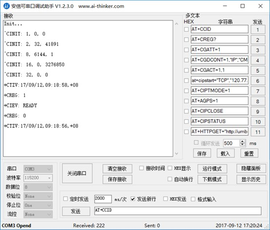
Power-on print output information
2. How to burn firmware
Preparation for burning firmware:
GPRS series module firmware release: http://docs.ai-thinker.com/gprs/firmware
Burning software download and burning tutorial: http://docs.ai-thinker.com/gprs_download
Three, related development
AT command debugging
A6/A9/A9G AT command operation examples (online documentation, will continue to update and debug DEMO) Please check AT command set for other usage
Secondary development
CSDK_Github open source information: https://github.com/Ai-Thinker-Open/GPRS_C_SDK
A9Tracker related functions
(Among A9Tracker related functions, the A9 module uses the base station positioning function, and the A9G module can choose to set the base station positioning function or the GPS positioning function, and upload the current position information to WeChat or app regularly. When positioning indoors, due to GPS signals Too weak, it is recommended to set the base station positioning function. For details, please refer to the following documents)
- A9/A9G 10-minute docking with Gizwits to create your own product tutorial: http://www.jianshu.com/p/e3d86a263be5
Fourth, common problems
1. Module power-on printing information
Under normal circumstances, the sign of the module power-on initialization is +CIEV: READY. The actual module requests data from the base station when it is initialized, and will issue the date, zero time zone time and time zone information. Due to network reasons, it will be in READY Output afterwards. Of course, after READY appears, it means that the module is powered on and initialized.
To
2. A9G baud rate adaptive
A9G has a baud rate adaptive function, the default baud rate is 115200. In the initial process of module power-on, the baud rate of the module can be modified. For example, the baud rate of my MCU is 9600, then when the module is just powered on, send a command AT (not only limited to this command, only used to adjust the baud rate), the module will automatically adjust the wave Special rate to 9600.
3. A9G indicator light description
| GPS status indicator | No positioning →0.5S | The flashing interval is 0.5S |
| Get positioning → 2S | Flashing interval is 2S | |
| GPRS status indicator | Unregistered network →0.5S | The flashing interval is 0.5S |
| During network registration →0.2S | The flashing interval is 0.2S | |
| Registered to the network successfully → 2S | The flashing interval is 2S | |
| For example, the registration is successful.On—(after 2s)——>off——-(after 2s)——>on |

