Full function test board V2.0
Full function test board V2.0
Product introduction
The ESP8266 full-function test version is a test version of an ultra-low power UART-WiFi module based on Espressif's ESP8266 developed by Shenzhen Anxinke Technology Co., Ltd., which can facilitate secondary development and accelerate product prototype design.
The addition of WIFI is largely used for convenient interaction with operators, and exchange of operating data and equipment through cloud servers, which is free for everyone to use!
Anxinke Ai-CloudV2.0 was recently launched. The Anxinke team successfully connected the full-function test board with Ai-CloudV2.0. Please refer to the tutorial on this page to upgrade the relevant firmware. In addition, Anxinke’s old Ai-CloudV1. 0 interface is about to close
Technical Specifications
- Support wireless 802.11 b/g/n standard;
- Support STA/AP two working modes;
- Support standard TCP/UDP Server and Client;
- Serial port baud rate: 110/300/1200/2400/4800/9600/19200/38400/57600/74800/115200/230400/460800/921600bps;
- Serial port data bits: 5/6/7/8 bits;
- Serial port parity check: none;
- Serial port stop bit: 1/2 bit;
- Lead ESP8266 GPIO 0/2/4/5/9/10/12/13/14/15/16/ADC/EN/UART TX/UART RX;
- RESET reset;
- DIP switch configuration function;
- Two-position DIP switch realizes serial port expansion switch between MCU and ESP8266;
- WiFi working current: continuous sending: ≈70mA (200mA MAX);
- Wireless transmission rate: 110-460800bps;
- Working temperature: -40℃~+125℃
- Test version size: 100mm*100mm
Attention! ! !
The full-function test board V2.0 is a MCU+WIFI structure, you need to follow the tutorial to burn the 2.0 firmware of the wifi module (the factory firmware cannot connect to the 2.0 cloud server, and the example operation cannot be completed), and then burn the single-chip program, Then follow the tutorial instructions to complete the APP communication.
In this mode, the user cannot directly send AT commands to the control module through the serial port. If the user wants to send the AT commands to the control module directly through the serial port, please proceed directly to the third step.
Quick start
1. APP download link:
2. Full-function test board MCU factory firmware and source code download address: includes firmware source code
3. The latest firmware download address of ESP8266 module: AiCloud2.0 AT firmware
One, burn ESP8266 module
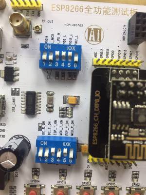
1. Plug the USB cable into the full-function test board and move the DIP switch according to the picture
2. Download the 2.0 cloud firmware compressed package, and burn it according to the burning method in the picture in the compressed package: 2.0 cloud firmware
3. Download the burning tool: Debugging tool collection
4. Refer to 如何为 ESP 系列模组烧录固件 for programming.
2. MCU burning Hex firmware
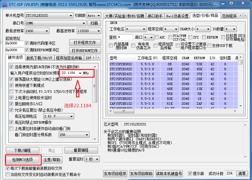
1. The MCU adopts STC15L2K32S2, and the download tool can be downloaded on the official website of Hongjing http://www.stcmcu.com/;
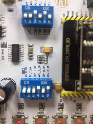
2. Open the STC-ISP tool, plug the USB cable into the full-function test board, slide the DIP switch according to the picture below, and then click the check MCU option, the module will automatically complete the software configuration;
3. Click “Open Program File”, select the Hex firmware of the MCU, and note that the IRC frequency when the user program is running is “22.1184MHz”;
Test program
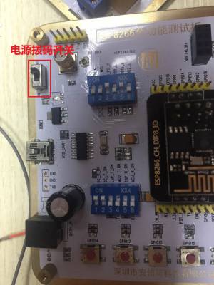
1. Flip the DIP switch according to the figure below, and turn the power switch to ON.
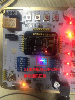
2. When the 51 single-chip microcomputer and ESP8266 communicate normally, the red, green and blue lights are on at the same time, as shown in the figure below.
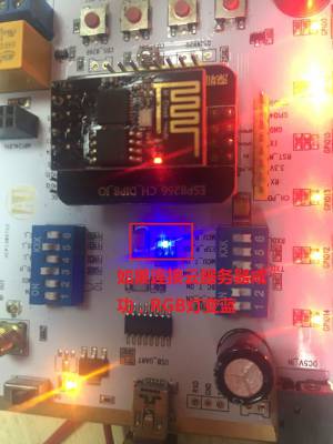
3. After waiting for a few seconds, if the RGB light turns red, it proves that the ESP8266 module is started for the first time. At this time, it enters the network configuration mode, please refer to step 6 for the network configuration mode. If the RGB light turns blue, it proves that the connection to the cloud server is successful. If the RGB lights keep on at the same time and there is no change, it proves that the router or cloud server is not connected, please check whether the network is normal.
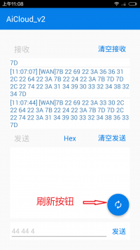
5. Enter the control interface, click the refresh button, the page will switch to the cloud function test board test page, as shown in the figure below.
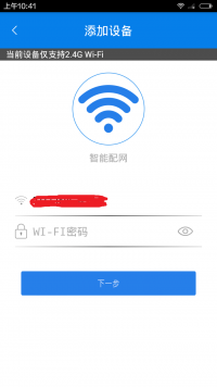
6. Click the MCU_P1.4 button on the full-function test board to enter the network configuration mode. At this time, the RGB red light turns on and returns to the main interface of the APP device. Click the “+” button in the upper right corner to enter the WiFi network configuration interface, and follow the instructions on the page Complete the network distribution steps, as shown in the figure below.
3. How to debug the wifi module on the development board separately
Debugging tutorial: http://bbs.ai-thinker.com/forum.php?mod=viewthread&tid=15&extra=page%3D1
Schematic download: esp8266_full_tester_sch_v2.0.pdf
ESP8266 full-featured beta version purchase address: https://item.taobao.com/item.htm?spm=a1z10.1-c-s.w11956625-15614796069.150.IJ6Yp2&id=41107235838
After purchasing this product, if you want to get the latest information about this product or other product information, you can visit our website: http://www.ai-thinker.com/
Shenzhen Anxinke Technology Co., Ltd. 2017-4-18


