Full-function test board
Full-function test board
Product introduction
The ESP8266 full-function test version is a test version of an ultra-low power UART-WiFi module based on Espressif's ESP8266 developed by Shenzhen Anxinke Technology Co., Ltd., which can facilitate secondary development and accelerate product prototype design.
Based on Espressif's ESP8266 module, realize the function of serial port to WiFi. The module has the following characteristics:
- WiFi uses industrial-grade chip ESP8266, which can support a full range of ESP8266 modules.
- You can use ESP8266 chip or module to directly complete the whole hardware core design (because ESP8266 includes WIFI and 32 system SOC) and there are enough pins. (SDK method)
- Advantages: Minimize system cost and volume
- Disadvantages: novices need a week to half a month to familiarize themselves with the code study
- You can use ESP8266 chip or module + external MCU to realize system functions. (AT method)
- Advantage: Only need to know a few AT commands to realize network communication with external MCU! The development speed is fast.
- Disadvantage: Increased external CPU cost
- Application design of terminal APP, including IOS and Android
The addition of WIFI is largely used for convenient interaction with operators, and exchange of operating data and equipment through cloud servers. In addition to the functional realization, the beautiful and concise interface can give users a better sensory experience. This requires the combination of software and hardware, and the realization of some simple or complex communication protocols, which often require a professional development team to complete. The investment in this area is second only to the development of the cloud platform. Anxinke also considers these for customers. And it is free for everyone to use!
In addition, our cloud services are released for use by factories or other institutions. At the same time, we also provide individual customers with some free cloud servers that can be used by customers for a long time. In addition, I want to add: For the powerful and relatively large-scale Gizwits Cloud, our software and hardware also provide comprehensive support. Therefore, our demo kit supports Anxinke Cloud and Gizwits Cloud!
For more WiFi module beta version and AiCloud information, please refer to: http://www.ai-thinker.com
Supporting Android app download: http://yun.baidu.com/s/1c1ERcXE#list/path=%2F
Technical Specifications
- Support wireless 802.11 b/g/n standard;
- Support STA/AP two working modes;
- Support standard TCP/UDP Server and Client;
- Serial port baud rate: 110/300/1200/2400/4800/9600/19200/38400/57600/74800/115200/230400/460800/921600bps;
- Serial port data bits: 5/6/7/8 bits;
- Serial port parity check: none;
- Serial port stop bit: 1/2 bit;
- Lead ESP8266 GPIO 0/2/4/5/9/10/12/13/14/15/16/ADC/EN/UART TX/UART RX;
- RESET reset;
- DIP switch configuration function;
- Two-position DIP switch realizes serial port expansion switch between MCU and ESP8266;
- WiFi working current: continuous sending: ≈70mA (200mA MAX);
- Wireless transmission rate: 110-460800bps;
- Working temperature: -40℃~+125℃
- Test version size: 100mm*100mm
Quick start
Test premise
1. ESP8266 full-function test board (support all Anxinke modules)
2. The supplied 5V power adapter and USB cable
3. The test APP software smarthome on the mobile phone. Warm reminder: Only the latest firmware 1.1.1 and later versions of Anxinke can support Internet cross-regional control! This version of the module and development board was only available to the market on June 25, 2015. The previous WIFI module can be used after cloud upgrade. The WIFI module is already equipped with
There is the latest AT cloud firmware, and the STC microcontroller on the board is also programmed to control this AT type ESP8266 to complete data transmission. So no need for yourself
Burn again! And the dial switch is also in the normal position, you don't need to move it again. All you have to do is to connect the power supply and power on.
{:esp8266:boards:full_function:Image_002.jpg?320×304}}
When leaving the factory, the position of the DIP switch and before power-on (it is better to use the supplied 5V power supply).
1 Enter setting state
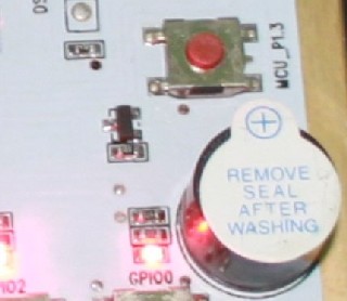
Let the device know your home Internet account and password: Before powering on, press and hold the MCU_P1.3 button
Don't let go until you hear a beep and the blue indicator light flashes! At this time, the system enters the state of obtaining your account password! Is the so-called
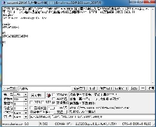
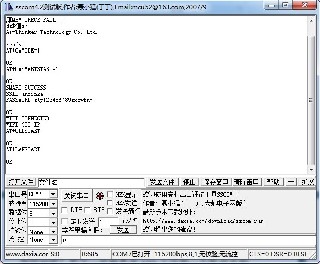
Smartlink opens the serial port debugging tool. You can see the following picture on the serial port interface.
Open your APP software, open your mobile WIFI, and select your home router.
2 Get Internet account and password
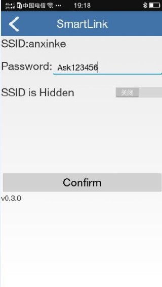
Click smartlinke in the above picture to enter the interface as shown in the figure. Enter your PASSWORD: Internet password, and then click confirm. After the device obtains the Internet account and password sent by your mobile phone, the three-color light stops flashing, which means the acquisition is successful! Success!
After obtaining the password, you can get the information module in the picture above to automatically connect to the Anxinke server.
3 Register an account
Since you want to use the APP on your mobile phone, your mobile phone must also log in to the server. The server does not log in when you want to log in. You have to register an account and password, right? The next step is to register an account name and password on the APP.
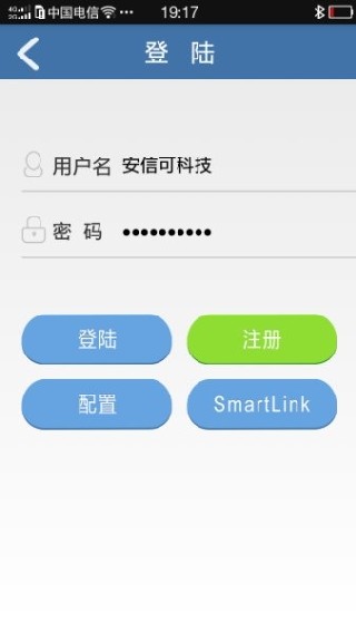
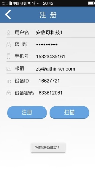
Open the mobile APP and click the “register” button! Just enter your name and set a password. In addition, it’s better to fill in the real phone number and email address, because you will need to retrieve the password later.
In order to avoid malicious registration, you must bind a real device ID and device password when you register. The device ID and device password here do not need to be filled in manually, just click Scan to get it automatically.
Principle: After the test platform obtains the Internet account and password, it will connect to the local router, which means it is in the same local area network as the mobile APP. But the mobile phone APP does not know the account and password of the WIFI on the test board. At this time, you click Scan, and the mobile phone will scan from the IP address 00 to 255. When the module receives the scan information, you can get the IP and port of the mobile phone from the information. , And the module returns its own device ID and device password to the APP. In the next step, click Register, and the phone will carry a legal device ID and a device KEY (password) to register with the server!
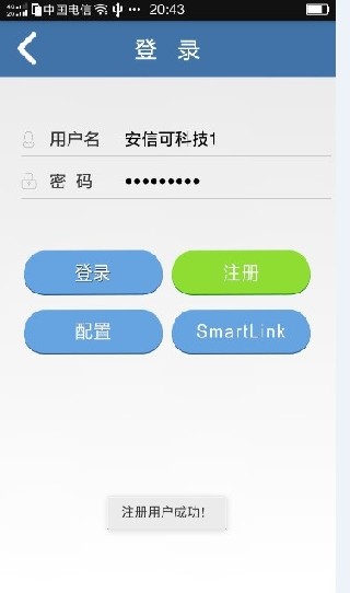
After successful registration, the system will prompt the successful registration! If this module has been registered, it will display registration failure!
After scanning successfully to obtain ID and KEY password, click Register
After successful registration, the username and password will be automatically recorded. At the same time, the server will remember your information.
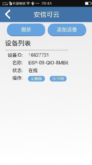
Sign in, and the device just now will appear in the device list after success!
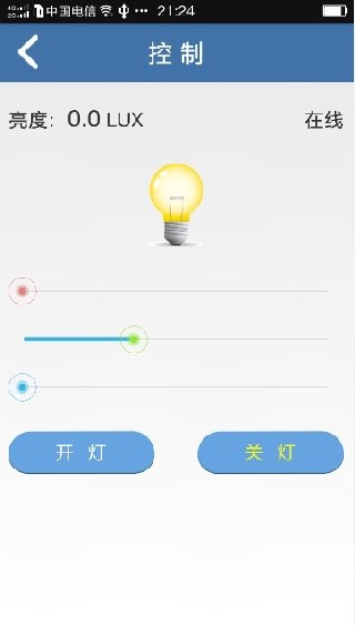
4 Control
In this interface, you can switch the relay on the test board, and you can also control the brightness of the red, green and blue lights on the board by dragging the bar! And the data uploaded from the test board can also be displayed on the APP than the upper left corner of the brightness! The above part of the source code is open, you can make simple modifications to complete your own IoT system! You can modify the 51 MCU program to complete the hardware execution part, and modify the APP to complete the interface control part!
Remind again
Before powering on the test board, press P1.3 and then power on. The LED on the system will flash once during the whole process. Wait for the mobile phone to send the Internet account and password to the module via SMARTLINK. The test board will stop flashing after obtaining it! After opening the test board, nothing is done. You can connect to the cloud within 5 seconds and be controlled!
You can rent Ali’s servers and run Anxinke’s cloud platform code to keep your customer information in your own hands, and you can change the code to achieve special new functions. Factory users build servers in Ali and log in to your own exclusive After the cloud service, enter your user name and password to enter the management interface to manage and view your users and devices! From then on, the cloud is completely yours.
The equipment management and user management have been stably realized. The necessary functions such as data forward and reverse control, user abnormal information management, etc., can be used by customers with confidence to make their own products, and stability and security are guaranteed.
Purchase and tool address
Schematic download: esp8266_full_tester_sch_v2.0.pdf
APP source download: smarthome_src_2015_06_15.7z
APK download: smarthomev3.7.apk.7z
MCU program download: v2.0_iot_full_test_board_mcu_src.zip
ESP8266 AT firmware download: ESP8266 SDK发布
ESP8266 full-featured beta version purchase address: https://item.taobao.com/item.htm?spm=a1z10.1-c-s.w11956625-15614796069.150.IJ6Yp2&id=41107235838
After purchasing this product, if you want to get the latest information about this product or other product information, you can visit our website: http://www.ai-thinker.com/
Shenzhen Anxinke Technology Co., Ltd. 2016-12-19

