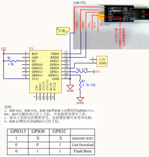
port are connected properly);
2. Pull down GPIO0, open the serial port tool, and observe the print information after the module is started or reset under the baud rate of “74880”;
3. If the following red characters appear, it is considered that the module has entered the download mode (the following value of “7” is ignored), and the download can be performed normally.
``ets Jan 8 2014,rst cause 1, boot mode:(1,7)
Please refer to the following circuit:
;
 ^How to ensure that the “ESP32” module correctly enters the download mode:^
1. First, ensure that the module can run normally (that is, ensure that the power supply and serial port are connected properly);
2. Pull down GPIO0, open the serial port tool, and observe the print information after the module is started or reset under the baud rate ``115200
3. If the following red characters appear, it is considered that the module has entered the download mode, and you can go to download normally.
Rst:0x10 (RTCWDT_RTC_RESET),boot:0x3 (DOWNLOAD_BOOT(UART0/UART1/SDIO_REI_REO_V2))
``waiting for download
===== ESP8266 Flash address configuration=====

The configuration options during burning are related to the configuration during compilation.
When compiling the SDK, the console will prompt the burning address of the bin file, the configuration is different, the burning address and the required files are also different

We divide into two situations according to the different burning files: support cloud upgrade and not support cloud upgrade

In addition, according to the different flash capacity, we have to adjust the burning address of the bin file

The firmware that supports cloud upgrade will be divided into 2 areas in the flash, one is used to run the program, the other is used to save the upgraded firmware,
When running user1 to upgrade, the program will download the firmware to user2. After the download is completed, it will be started from user2 at the next startup and replaced in turn to achieve cloud upgrade.

user2 is only used for upgrading, users do not need to download user2.bin when burning, here is only the storage location of user2
Note 1: Espressif may change these burning locations in different versions of the SDK. The following instructions are for reference only, and it is recommended that the console output information during development prevail.
Note 2: The merged firmware already contains the address information, only need to be programmed to the 0x0 address.
==== Cloud upgrade is not supported (NoBoot mode) ====

^File name^8Mbit address allocation^16Mbit address allocation^32Mbit address allocation^Remarks^
|eagle.flash.bin|0x00000|0x00000|0x00000|Main program, generated by code compilation|
|eagle.irom0text.bin|0x10000|0x10000|0x10000|Main program, generated by code compilation|
|esp_init_data_default.bin|0xFC000|0x1FC000|0x3FC000|Provided by Espressif in the SDK|
|blank.bin|0xFE000|0x1FE000|0x3FE000|Provided by Espressif in the SDK|

====Support cloud upgrade (Boot mode)====

^File name^8Mbit address allocation^16Mbit address allocation^32Mbit address allocation^Remarks^
|boot.bin|0x00000|0x00000|0x00000|Provided by Espressif in the SDK, it is recommended to always use the latest version|
|user1.bin|0x01000|0x01000|0x01000|Main program, generated by code compilation|
|user2.bin|0x81000|0x81000|0x81000|Main program, generated by code compilation|
|esp_init_data_default.bin|0xFC000|0x1FC000|0x3FC000|Provided by Espressif in the SDK|
|blank.bin|0xFE000|0x1FE000|0x3FE000|Provided by Espressif in the SDK|

=====ESP32 Flash address configuration=====

When ESP32 is compiled, the Partition Table is configured through make menuconfig
Support Single factory app, no OTA, Factory app, two OTA definitions, Custom partition table CSV respectively
Note 1: Espressif may change these burning locations in different versions of the SDK. The following instructions are for reference only. It is recommended to use the console output information during development as the standard.
Note 2: The merged firmware already contains the address information, only need to be programmed to the 0x0 address.
==== OTA is not supported====
By default, bootloader.bin, app_demo.bin, partitions_singleapp.bin are generated

^bin file ^burning address ^description ^
|bootloader.bin |0x1000 |Second-level boot program, compiled and generated by SDK code|
|app_demo.bin |0x10000 |User main program, generated by code compilation |
|partitions_singleapp.bin |0x8000 |Partition information, automatically generated by code |


====Support OTA====

====Custom====
Reference https://github.com/espressif/esp-idf/blob/master/docs/partition-tables.rst
=====Burning download=====
Description:
*Remember to connect the module according to the above circuit before powering on.

*The 3.3V power supply is guaranteed. Generally, the output current of the external power supply must be 500mA and above.

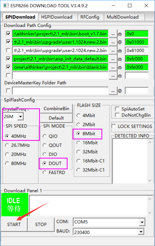
1. Open ESP FLASH TOOL, configure the bin file and burn address according to the previous chapter

2. Need to configure crystal frequency, SPI SPEED, SPI MODE, Flash Size, serial port number and baud rate, etc. Here, the baud rate can be selected as large as possible to save time. If it prompts ERROR, please lower the baud rate. Take ``8Mbit
Flash as an example:
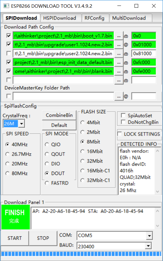
3. After the configuration is completed, power on the module to enter the download mode, and then click [START] to start programming until the programming is completed:
4. “After the download is complete:”
* Please switch the boot mode of ESP8266 to flash boot, namely GPIO15→0, GPIO0→1, GPIO2→1.
* You can view log and print through the serial port debugging tool or perform serial port command interaction.
How to merge firmware
How to erase the entire Flash
Use the following file to burn to Flash 0x0 address
End
If no error is prompted during the execution of the above steps, the programming is successful.

